[This text is machine generated and may contain errors.]
Electronic Instruments for the Musician
K-A-MOOG CO-
TRUMANSBURG, NEW YORK 14886 *? AREA CODE. 607 387-9200
October, 1964
MODULAR ELECTRONIC INSTRUMENTS
FOR
GENERATING AND PROCESSING AUDIO SIGNALS
The instruments to be described are the first group of a
system of compatible signal generating and processing modules,
designed to perform basic functions required in electronic
muSic composition, and in many other audio signal processing
applications. The value of these modules is attributable to
this unique combination of the features:
1. Many of the instruments are voltage-controlled. The
relation between the magnitude of the controlling voltage and
the controlled variable of the instrument (e.g. frequency of
the oscillator or gain of the ampifier) is mathematically
Simple (usually linear or exponential) and accurate within speci-
fied narrow limits over a wide range.
2. The input and output levels of the instruments are
arranged so that the instruments may be connected in tandem
with a minimum of gain or impedance adjustment.
3. The entire system of modulGs utilizes solid state cir-
cuitry and is powered from 2common regulated power supply.
4, The panels of all instruments are 9-1/2" wide (one-
half the width of a standard 19" relay rack) and integral mul-
tiples of 1-7/8" high.
VOLTAGE CONTROL
In much electronic signal processing equipment, the func-
tional variables are determined by passive electronic components.
For instance, the frequency of a typical audio test oscillator is
determined almost entirely by the value of two resistors and two
capacitors. As another example, the gain of a typical amplifier
is stabilized by a feedback network consisting primarily of re-
sistors, Such instruments are useful where stability of perfor-
mance over long periods of time is important. However, in the
production of electronic music, and in other application invol-
ving the rapid changing of signal variables, instruments whose
Page 1
aon ERs
2168
t %
54 -\9?
functions are controlled by the effect of an applied voltage upon
the characteristics of non-linear (usually active) components with-
in the instrument, are generally of greater value.
The usefulness of a voltage-controlled instrument is further
enhanced if the voltage controls the instrument variable in a
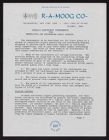
Simple, predictable way. As an illustration, consider a relaxa-
tion oscillator in Figure 1, which consists of a charging capac-
itor, a discharging element such as a neon bulb or a unijunction
transistor, and a source of constant current. The constant cur-
rent charges the capacitor until the capacitor voltage reaches
the breakdown voltage of the discharging element. The discharg-
ing element abruptly conducts away a portion of the capacitor
charge, then switches off. The process repeats, giving rise to
a s''-wtooth waveform across the capacitor. The frequency of the
oscillation is directly proportional to the total charging cur-
rent. Thus, adding a given current will increase the frequency
a fixed amount, regardless of the magnitude of the "standing
current" to which the given current is added. Stated more pre-
cisely, the frequency is a linear function of total charging
current.
In the production of music, however, constant frequency
differences are of little value. The fundamental subjective
concept of frequency change in music is the INTERVAL, which is
a ratio of two frequencies. In order to be musically valuable
therefore, a voltage-controlled oscillator should generate a
fixed frequency ratio (percentage change in frequency) for a
given control voltag2 change, In mathematical language, what
zrequency be an exponential function
= Beg
is desired is that the
of the control current.
To appreciate the great utility of a voltage-controlled
oscillator in which the frequency is exponentially related to
the control voltage, consider the circuit arrangement shown in
Figure 2. In addition to the reli..ation oscillator itself (c),
the voltage control consists of (a) a linear adder which pro-
duces a voltage proportional to the sum of all the input vol-
tages and (b) an exponential operator that produces a current
proportional to the exponential of its input voltage. The
oscillator frequency is then proportional to the exponential
of the sum of the input (control) voltages.
By uSing one control voltage input, the above oscillator
can be used as a monophonic ps itch SONG RAtOR. Taking. the con-
trol voltage from lly spaced taps on a potenti-
ometer divider, luces an anced a tempered scale. This arrange-
ment is shown in Figure 3. To produce vibrato or other periodic
variations in frequency, an alt?ornating control voltage is ap-
plied to another co ntrol input. The width of vibrato (i.e. the
ratio of frsquency change to center frequency) remains constant
as the center frequency (perceived pitch) is varied. The arrange-
ment for producing vibrato is shown in Figure 4. The third con-
trol input may be used to transpose a frequency pattern. Thus,
Page 2
CHARGING
CAPACITOR
9 SAWTOOTH
VOLTAGE
, "A VEFORM
CURRENT 3 |
SOURCE \ : eee /
| - e? BREAKDOWN
: DISCHARGE
FIGURE 1: RELAXATION OSCILLATOR --~-
atte
RELAXATION
arrow
| : OSCILLATOR
E1 O\_| LINEAR EXPONENTIAL (c)
oc) MOB t Foe
E2 0 tx) CONVERTER 3 BEG | ?
2 Bd
a?
94.W TOOTH
OUTPUT
WAVEFORM
FIGURE 2: ADDITION OF LINEAR ADDER AND
EAR@EENTIAL CONVERTER
LINEAR >? LO EAPONENTIAL
ADDER CONVERTER
ee
Cee tee
oes
FIGURE 3: PRODUCTION OF EQUALLY
TEMPERED SCALE
| MENEAR , TO EXPONENTIAL
VOLTAGE" \ ADDER CONVERTER
:
;
ane en
a ee,
re
FIGURE 4: INTRODUCTION OF
VIBRATO
Page 3
a ramp (very slow sawtooth) voltage applied to control input #3
will continuously slide the pitch paptern being "played".
The rate at which the occillator frequency can be modulated
by alternating control voltages extends well beyond the audio fre-
quency range. Thus, by modulating with audio frquency control
voltages, the oscillator generates audible sidebands that are not
harmonically related to the center frequency. An enormous variety
of complex tones can be created in this manner.
A& voltage-controlled amplifier in which the gain is propor-
tional to the exponential of the sum of the controi voltages is
equally valuable in the composition of the music. It is known that
the amplitude of an audible sound is roughly proportional to the
exponential of the subjective sensation of loudness. Thus, a
given change in control voltage will seem to change the loudness
of the signal the Same amount over a wide range of average loud-
ness. The generating of gain "envelope" control voltages iS ex-
tremely easy. For instance, exponential envelope decays are gen-
erated by falling ramp voltages, and "reverse exponential" en-
velopes, usually produced by reversing a tape-recorded segment
of an exponetially decaying sound, are generated by rising ramp
voltages.
aga The usefulness of a voltage-controlled amplifier is further
.enhanced by balancing the amplifier so that control voltages vari-
ations do not feed through to the output. With this feature, the
amplifier can perform as an ideal amplitude-modulator, The fre-
quency spectrum of the Signal can be modified by the introduction
of rapidly-varying control voltages. Furthermore, the modifi-
cation of the signal frequency spectrum is independent of the
Signal amplitude.
The voltage-controlled oscillator and voltage-controlled
amplifier are the basic moduaar instruments of an extremely ver-
Satile signal generating and processing system. The oscillator,
in addition to providing a signai which can be processed further,
also supplies periodic control voltages to modulate other instru-
ments. The amplifier forms amplitude envelopes and modifies the
harmonic structure of the signal, as mentioned above. It can also
be connected as a voltage-controlled filter by placing passive re-
active components in a feedback loop around the amplifier. Vir-
tually any simple filter configuration can be arranged in this
way. In most cases, the characteristic frequency of the filter
will be proportional to the exponential of the control voltage.
STATUS OF AVAILABILITY OF THE MODULAR INSTRUMENTS
Voltage-controlled modular instruments for audio signal pro-
cessing have been undergoing development at the R.A. Moog Co. for
several years. During the past six months, prototype designs have
actually been used to compose and perform music. As a result of
this experience, certain features have been found to be generally
Page 4
valuable, and have been incorporated in the instruments listed
below. These instruments are now in pilot production. In the
near future, more modular instruments will be placed in pilot pro-
duction, and extensive data will be gathered on instruments cur-
rently being produced.
In a few months, a comprehensive catalog will be prepared.
In the meantime, R.A. Moog Co. invites communications from those
who are interested in the generating and processing of audio
Signals, and who wish to submit suggestions or problems for our
consideration.
TENT "SVE SPECIFICATIONS OF CURRENTLY AVAILABLE ECUIPMENT
All instrument panels are 9-1/2" wide and integral multiples
of 1-7/8" high. Mounting holes conform to standard relay-rack
mensions. Power supply requirements are +12 volts and -6 volts
regulated DC,
MODEL $01 VOLTAGE- CONTROLLED OSCILLATOR
Relation between Control Voltage and Oscillator Frequency:
Control voltage increase of 0.75 volts will double Oscillator
Frequency.
Frequency range: One of six frequency ranges is selected by
a charging capacitor selector switch. The total range, and
the range of greatest accuracy are listed below:
Range in which Fre-
quency is proportional
to exponential of con-
trol voltage to with-
Range Total Frequency Range in + 1%
LO 90 cps 1-O cps - 25 cps
32! 1 KC 15 cps -- 500 cps
16' 2 KC 30 cps - 1 KC
gS! .4 KC ; 60 cps - 2 KC
. 4? 8 KC 120 cps - 4 KC
2! 15KC 240 cps - G6KC
Output Waveforms: Sawtooth, sine-like, and rectangular pulse.
Width of pulse is variable by a panel control.
Size: Panel size is 9-1/2" X 3~1/2 . Depth in back of panel
is ?",
Price: $ 145.00
Page 5
MODEL 902 VOLTAGE- CONTROLLED AMPLIFIER
Input Impedance: &,000 ohms
Output Impedance: 6,000 ohms
Maximum Voltage Gain: 100
Range of Voltage Gain: Greater than 80 db
Gain Range in which gain
is proportional to expon-
ential of control voltage
to within 1%: -l1 -- 100 (60 db)
Signal-Noise ratio at vol-
tage gain of 50 and input
voltage of oSmv: better than 70 db
Maximum Signal voltage input: 10 mv
Total harmonic distortion at
maximum gain and input vol-
tage of 10 mv:
Frequency response:
Size: $125.00
MODEL 910 POWER SUPPLY
Output Voltages: +1lz volts and -S volts
~
Maximum Oitput Current: Z2 amperes
Regulation: + .1 % for loads of 0-2 amps and line voltages
of 105-130V
size: Panel size S-1/2" KX 7". Depth behind panel is 6",
Price: $120.00
MODEL $50 FIVE OCTAVE KEYBOARD
supplies control voltage to an oscillator or bandpass filter
for equal temperament tuning. Also generates two independently
adjustable envelope control voltages when any key is pressed. |
Keyboard is housed in hand-finished natural walnut case.
Price: $220.00
Page 6
MODEL 955 "SLIDE-WIRE' CONTROLLER
supplies continuously-variabie control voltage to any vol-
tage-controlled instrument. Consists of two-foot long gold-
plated taut band which is strung over a high-resistance wire.
The resistance wire is connected to the power supply, thus
forming a long potentiometer. The taut band is pressed down
at a point determined by the control voitage desired.
Price: $35.00