
FIXED FUZE.
[note]
Directions for Loading and Handling the Shell.[note]
The Shell is not loaded with a bursting charge; but is to be filled with powder, through the charging hole, which must then be carefully plugged with a plug made of beech or of oak, and not of pine. The time of burning of the fuze is marked in seconds on THE LEADEN PATCH which covers the fuze. Before firing REMOVE THE LEADEN PATCH, with the point of the instrument provided for that purpose, or the shell will fail to explode. This must be done after the shell is put into the mouth of the gun, and, and the same time, the surface of the composition much to PRICKED UP so as to raise the fibres of the quick match and thus ensure its taking fire when the gun is discharged.
The manner in which the shell is strapped shows that it is not intended that the fuze shall lie directly in front. If should be placed TOWARD THE MUZZLE, ABOVE THE CENTRE OF THE BORE AND IN THE VERTICAL PLANE which cuts THE AXIS OF THE BORE. The shell being somewhat heavier at the fuze hole than at any other part, by this position of the fuze the greatest regularity of flight, together with the longest range, will be obtained. If, by any accident, the shell should slip in its straps, so that the fuze hole shall be covered or its position deranged, hold the shell firmly and tap the sabot with a mallet or light hammer until the fuze is brought in a direction, which, when the shell is placed in the gun, shall form an angle of about 45 degrees with the axis of the bore.
Instead of ramming the shell, PUSH IT HOME and avoid turning the rammer in this operation for fear of altering the position of the fuze.
In loading, even a grummet is unnecessary, and may hinder the fuze from igniting. The sabot to which the shell is strapped will prevent it from wither rolling or sliding out of place.
Officers are particularly enjoined not to explain the character of these fuzes, and the manner of fitting them, to persons unconnected with the service of the United States.
John L. Porter
U. S. Naval Constructor 1860
Pensacola Navy Yard

On the 29th of December 1882 I was elected a Superintendent of the Norfolk County Ferries, the following members of the committee being present Wm. A. McWherter, chairman, Wm H. Peters, R. I. Neely, T. I. Nottingham, Wm H. Douglas Chas. H. Graham, committee present, and went on duty on the 1st of January 1883. So soon as C. W. Murdaugh, who had been appointed judge of the Hustings Court by the Readjuster Legislature, assumed control, he removed Mssrs. Peters and Neely two of the most efficient members of the committee and appointed in their stead, Ambroso Lindsey and Andrew Hopkins, Readjusters. Mr. Lindsey remained but a short time on the committee and resigned and Mr. John White (Readj.) was appointed in his stead, so the committee now stands on the first day of June:
Wm. A. McWherter, Chair, Republican
W. N. Douglas Do
T. I. Nottingham Democrat
Chas. H. Graham Readjuster
Andrew Hopkins Do
John White Do
My friends on this committee are the first three named, and to whom I am indebted for my position today, June 9th 1883, but don’t know what a day may bring forth in this time.

Preface
This little book contains what is requisite for a candidate to know before he can pass a creditable examination as a Constructor in the U. S. Navy. It was compiled by myself after my examination as such for a reference, for it will readily be seen after a full perusal of it, that it would be next to impossible for any person to retain it all for any length of time, but if the book is at hand, he could soon refresh himself in case he forgot any part of it. Everything in the book is made plain and easy to be understood. The workings of the displacements, centre of gravity, meta centre, centre of effort of the sails, scale of capacity, etc. etc. have been taken from Steele’s works on Naval Architecture and are the best and plainest now in use, as also the laying down of the lines, bevellings, etc. etc. etc.
John L. Porter
U. S. N. Constructor
1860
Addition of Vulgar Fractions
Add 1 . 2 and 3 together
7 7 7
1 x 7 x 7 = 49
7 x 2 x 7 = 98
7 x 7 x 3 = 147
7 x 7 x 7 = 49 (numerators 6)/(denominators 7 ans.)
--------------------------------------------------
Add 1 and 3 together
4 5
1 x 5 = 5
4 x 3 = 12
17 numerators}
4 x 5 = 20 denominators } = 17 ans.
20
---------------------------------------------------
Add 1 3 4 together
8 10 12
1 x 10 x 12 = 120
8 x 3 x 12 = 288
10 x 8 x 4 = 320
8 x 10 x 12 = 8)728 numerators} 91
= 8)960 denom.} 120 ans.
----------------------------------------------------
Add 5- 2 6- 7 4- 1 together Integers
3 8 2
2 x 8 x 2 = 32 5
3 x 7 x 2 = 42 6
1 x 8 x 3 = 24 4
3 x 8 x 2 = 48 )98 numer.
48 denom. 2 1 2 1
24 24
7. 1
24 ans.
-------------------------------------------------------
Addition is reversed.

Addition of Vulgar Fractions
Add 5 of 9 and 7 of 4 together
6 10 12 5 Sum
5 x 9 = 45 7 x 4 = 28 45 x 28
6 x 10 = 60 12 x 5 = 60 60 x 60
45 x 60 = 2700
60 28 = 1680
)4380 num.
60 x 60 = 3600 )3600 den = 1- 13 ans.
60
------------------------------------------------------------------------------
Addition of Compound Vulgar FractionsAdd 7 of a £ to 3 of a shilling
9 10
1 £ = 20 s. 1 s. = 12 d.
7 s d 3
9 ) 140 ( 15 6 2 10 ) 36 ( 3 3
9 3 30 5
50 2 ) 6 | = 3
45 )10 | 5
5 d
12
9 ) 60 ( 6 d
54
3 ) 6 = 2
9 3 2 and 3
3 5
2 5 10
3 x 3 = 5
15 ) 19 num 1 4
3 x 5 = 5 ) 15 den 15
s d
Sum 7 of one £ = 15 - 6 2
9 3
3 of one s. = - 3 3
10 5
s. 15.10 4
15 ans.
Addition is reversed
Subtraction of Vulgar Fractions
From 4 take 3 ans. 1
5 5 5
From 7 take 4 ans. 3 or 1
12 12 12 4
From 3 take 2
7 5
3 x 5 = 15
7 2 14
1
7 x 5 = 35 ans.
------------------------------------------------------------------------------
From 8- 2 take 6- 3
9 11
8- 2 = 74 6- 3 = 69
9 9 11 11
74 x 11 = 814
9 69 621
99)193 num. | = 1 - 94
11 x 9 = 99 | 99 ans.
94
99
------------------------------------------------------------------------------
From 1 of 9 take 1 of 4
2 10 4 9
1 x 9 = 9 1 x 9 = 4
2 20 20 4 9 36
9 x 36 = 324
24 4 80
) 244 = 61
36 x 20 = 4 ) 720 = 180 ans.
------------------------------------------------------------------------------
Reversed

Subtraction of Vulgar Fractions
From 6 take 1/8 6.8/0
1
5.7/8 ans.
From 3 take 3/16 16
3.0
3
2.13/16 ans.
From 100 take 9999/100 100
100 . 00
99 . 99
1/99 ans.
------------------------------------------------------------------------------
Subtraction of Compound Vulgar FractionsFrom 7/9 of a take 3/10 of a shilling
1 = 20 s. 1 s. = 12 d.
7 s. d. 3
9)140 ( 15. 6- 2/3 10 ) 36( 3 3/5
9 30
50 3- 3/5 2 ) 6/10 3/5
45 ____________
5 15.31/15 ans.
12 d.
9)60 ( 6
54 2/3 X 5/3 = 10/9
6/9 | 2/3
3 X 5 = 1/15 denom.
Subtraction is reversed.
Multiplication of Vulgar Fractions
Multiply 4/9 x 2/7 = 8/63 ans.
Multiply 1/12 x 3/8 = 3 | 3/96 | 1/32 ans
Multiply 12 3/5 x 7 2/3 12 3/5 = 63/5 . 7 2/3 = 23/3
63/5 x 23/3 = 1449/15 = 96 3/5 ans.
Multiplication not reversed.
------------------------------------------------------------------------------
Division of Vulgar Fractions
Divide 4/9 x 7/8 = 4/9 x 8/7 = 32/63 ans.
Divide 4/7 x 2/3 = 4/7 x 3/2 =12/14 or 6/7 ans.
Divide 1 1/2 x 4 8/10 = 3/2 x 10/48 = 6 | 30/96 = 5/16 ans.
Division is reversed.

Vulgar Fractions / Decimal Fractions Values
Same ValuesVulgar Fractions Same Values
Decimal Fractions
1/8 00.1
1/4 00.2
3/8 00.3
1/2 00.4
5/8 00.5
3/4 00.6
7/8 00.7
1 00.8
2 00.17
3 00.25
4 00.33
5 0.42
6 0.50
7 0.58
8 0.66
9 0.75
10 0.83
11 0.92
12 10.00
Addition of Decimal Fractions
Place tens under tens, hundreds under hundreds, etc. Then sum up as in whole numbers, and separate the integers from the decimals by a dot. Example add together
10.257 .. 5.393 .. 4.937 .. 3.873..2.92
10.257
5.393
4.937
3.873
2.92
27.380 sum
------------------------------------------------------------------------------
Subtraction by Decimal Fractions
Proceed as in the preceding rule then subtract as in whole numbers.
Example
Subtract 10.87686 from 21.59984
21.59984
10.87686
10.72298 ans.

Multiplication of Decimals
Multiply as in whole numbers and cut off as many figures from the product, proceeding from right to left, for decimals as there are decimal figures in the multiplier and the multiplicand.
Example, multiply 13.59876
by 15.58797
9519132
12238884
9519132
10879008
6799380
6799380
1359876
211.9770629172
_______________________________________________
To find the Decimal of any vulgar fraction, annex cyphers to the numerator and divide by the denominator.
Example. What is the decimal value of 3/4
" 4 ) " 3.00/(2.8 ) " ( " 75/100 ans
2.0/2.0
Duodecimals
Feet by feet give feet Ft.
Feet by primes give primes
Feet by seconds give seconds
Primes by primes give seconds
Primes by seconds give thirds
Primes by thirds give fourths
Seconds by seconds give fourths
Seconds by thirds give fifths
Seconds by fourths give sixths
Thirds by thirds give sixths
Thirds by fourths give sevenths
Thirds by fifths give eighths
How many square feet in a floor 35 feet 4 1/2 inches long by 12 feet 3 1/3 inches wide
Example
Feet
35 4 6
12 3 4
424 6 0
8 10 1 - 6
11 9 - 6 0
434 3 11 0 0 ans

Reduction of Vulgar Fractions
Reduce 72/96 to its lowest terms
Exam. 12 72/96 2 6/8 3/4 ans.
Reduce 9/27 to its lowest terms 9 9/27 1/3 ans.
------------------------------------------------------------------------------
Reduce 3/4 . 4/5 . 5/6 to a common denominator
Example 3 x 5 x 6 = 90 } numerators
4 x 4 x 6 = 96 }
5 x 5 x 4 = 100 }
4 x 5 x 6 = 120 common denominators
Result 90/120 x 96/120 x 100/120 ans.
------------------------------------------------------------------------------
Reduce 12 4/9 to an improper fraction /
Ex. 12
9
108
4 +
112/( 9)
------------------------------------------------------------------------------
Reduce 219/17 to its proper terms
17 ) 219 ( = 12 15/17 ans
------------------------------------------------------------------------------
Reduce 2/3 of 3/4 of 4/5 to a single fraction
Ex. 2/3 x 3/4 x 4/5 = 24/60 or 2/5 ans.
------------------------------------------------------------------------------
Reduce 5/6 of a penny to the fraction of a
Ex. 5 x 1 x 1 = 5 or 1 ans
6 12 20 1440 288
Reduction of Vulgar Fractions
Reduce 1/1584 of a day to the fraction of a minute
Ex. 1/1584 x 24/1 x 60/1 = 1440 180 20 10 ans
2584 298 22 11
------------------------------------------------------------------------------
Reduce 2/3 of a to its proper value
Ex. 20 s.
2 s
3 )40 ( = 13-1/3
------------------------------------------------------------------------------
Reduce 9/10 of a year to its proper quantity
Ex. 365
9
10 )3285 ( = 328 days 12 hours
------------------------------------------------------------------------------
Reduce 13 s. 4 d. to the fraction of a
Ex
s d d
13 - 4 = 160
2 ans
1 = 240
3
------------------------------------------------------------------------------
Reduce 10 s. 6 d. to the fraction of a
d.
10 s 6 d = 126
21 ans
1 = 240
40

Square Root
What is the 4th power of 2
Ex. 2 x 2 x 2 x 2 = 16 ans.
What is the square root of
5499025 (2345 ans
4_____
43 )1.49
1.29
464 ) 20.90
18.56
4685 ) 244.25
234.25
------------------------------------------------------------------------------
What is the square root of 7056/9216
Ex. 7056 (84 9216 ( 96
12 84 7 ans
96 8
64_____ 81_____
164) 6.56 186) 1116
6.56 1116
If the fraction be a sum that is one whose root cannot be exactly found reduce it to a decimal and then extract the square root.
Ex. What is the square root of 478/549
549 ) 478 ( = 870673 (.9334 ans
81____
183 ) 606
549___
1863 ) 57.73
55.89_
------------------------------------------------------------------------------
Square Root
What is the square root of 37 36/49
___________
Ex. 37- 36/49 = 1849/49 = 43/7 7 ) 43 (6 1/7 ans
42
1/7
What is the square root of 8-5/7
Ex. 8 5/7 = 8,7143 ( 2.954 ans
4
49) 471
441
585) 30.43
29.25
What is the square root of 20736
20736 (144 ans
1
24) 1.07
96
284) 11.36
11.36
Proof
1002 = 10,000
100 x 40 x 2 = 8,000
402 = 1,600
42 = 16
20,736
The square filled up.

Cube Root
What is the cube root of 99252847
99,252,847 ( 463 ans.
43 = 64
42 x 3 = 48 )352
) 99252
463 = ) 97336
462 x 3 = 6348 ) 19168
99252847
4633 = 99252847
Another mode
What is the cube root of
673,373,097,125 ( 8765 ans
83 = 512
161.373
82 x 3 = 192.
72 annex .49
7 x 3 x 8 =168.8
20929 x 7 = 146.503
14870097
872 x 3 = 22707.
62 annexed = .36
6 x 3 x 8.7 = 156.6
2286396 x 6 = 13718376
8762 x 3 = 2302128. 1151721125
52 annex = .25
5 x 3 x 876 = 1314.0
22303442.25 x 5 = 1151721125
Logarithms
Logarithms are a series of numbers or rather roots of numbers calculated in order to facilitate those operations which cannot be performed without extreme labour and delay by common arithmetic.
By means of a table of logarithms multiplication is performed by addition and division by subtraction.
The integer prefixed to a logarithm is called its index. Thus 2. is the index of the logarithm 2.2081725.
The logarithm of 10 is 1, of 100 is 2, of 1,000 is 3, of 10,000 is 4, etc.
When the number for which a logarithm is wanted lies between 1 and 10, 10 and 100, 100 and 1,000
Logarithms
. . . a reference must be to a table of logarithms.
The index of the logarithm of any integer or mixed number is always one less than the number of integer places in the natural number. Thus between 100 and 1000, it is 2, and 10,000 it is 3, etc. The index is generally omitted in tables for the sake of brevity.
To find the logarithm of any mixed decimal number.
Rule Find the logarithm as if it were a whole number, and prefix the index of the integer part.
Thus: the logarithm of 259.7 is 4147, to which if the index be prefixed the logarithm is 2.4147.
Logarithms
To find the logarithm of a vulgar fraction. Rule subtract the logarithm of the denominator from the logarithm of the numerator borrowing 10 in the index, when the denominator is the greatest. The remainder is the logarithm required. What is the logarithm of 5/9
10
Ex. Logarithm of 5 = 0.69897
“ of 9 = 0.95424
9.74474
------------------------------------------------------------------------------
Multiplication by Logarithm
Rule Add together the logarithms of the multiplier and the multiplicand. The sum is the logarithm of the answer required.
Multiply 9 by 253.
Ex. Logarithm of 9 = 0.95424
“ of 253 = 2.40312
3.35736
3.35736 is the logarithm of 2277 ans
Logarithms
Division
Subtract the logarithm of the divisor from the logarithm of the dividend. The difference is the logarithm of the quotient.
Divide 477 by 3
Ex. Logarithm of 477 = 2.67852
“ “ 3 = 0.47712
2.20140
Logarithm of 2.20140 is 159 ans
_______________________________________
Involution by Logarithm
Rule Multiply the logarithm of the root by the index of the power to which it is to be raised. The product is the logarithm of the answer.
Required the 5th power of 11.
Ex. Logarithm of 11 = 1.04139
x _ 5
5.20695
5.20695 is the logarithm of 161051 the answer.
Logarithms
Evolution
Divide the logarithm of the given number, by the index of the power. The quotient is the logarithm of the root. Example.
What is the cube root of 15625
Logarithm of .15625 = 4.19382.
419382 divided by 3 = 1.39794.
139794 = logarithm of 25 ans.
______________________________________
Rule of Three by Logarithms
Add together the logarithms of the 2nd and 3rd terms, and from their sum deduct the logarithm of the first term. The difference will be the logarithm of the answer.
Example.
If 110 gives 19 what will 94 give
100 : 19 : : 94
Log - 204139 : 197313 : : 127875
197313
3.25188 2nd and 3rd terms
deduct 2.04139 1st term
1.21049
1.21048 logarithm of 16.24 ans.
Algebra
+ into + produces +
- into + produces - This is for multiplication.
+ into - produces -
- into - produces -
In division the same rule is to be observed respecting the signs as in multiplication. That is: If the divisor and dividend are both positive, or both negative, the quotient must be positive. If one is positive and the other negative the quotient must be negative.
Addition
Add - 3bc - ax - 2ab my
to - bc -3ax - ab - 3my
- 5bc -2ax - 7ab - 8my
- 9bc -6ax -10ab -12my
Add + 6b +4b +5bc - 2 hm - dy + 6 m
to - 4b -6b - 7bc - 9 hm - 4 dy -__ m
+ 2b -2b - 2bc - 7 hm - 3 dy + 5 m
Algebra
Subtraction
From +28 16 b 14 da -28 - 16 b - 14 da
Subtract +16 +12 b + 6 da -12 - 4 b - 6 da
+12 + 8 b + 8 da -16 - 12 b - 8 da
This case is the same as in arithmetic. The two next examples do not occur in common arithmetic.
From +16 b 12 b 6 da -16 - 12 b
Subtract +28 b 16 b 14 da -28 -16 b
Div. -12 b - 4 b - 8 da +12 4 b
From + 28 + 16 b + 14 da - 28 - 16 b
Subtract - 16 - 12 b - 6 da + 16 + 12 b
Div. + 44 28 b 20 da - 44 - 28 b
From 2 xy - 1 h + 3 bx hy - ah
Subtract - xy + 7 3h – 9 bx 5 hy – 6 ah
Div. 3 xy – 8 2h + 12 bx - 4 hy + 5 ah
From 3 abm h + 3 bx -17 + 4 ax
Subtract - 7 abm 3h – 9 bx -20 - ax
Div. 10 abm - 2h + 12 bx + 3 + 5 ax
Algebra Multiplication
Multiplication in whole numbers is taking the multiplicand as many times as there are units in the multiplier.
Mul. 9 ab 12 hy 3 dh 2 ad 7 bdh
Into 3 xy 2 rx ny 13 hmy x
27 abxy 24 hyrx 3 dhny 26 adhny 7 bdhx
Multiply d + 2 xy 2 h + m 3 hl + 1 2 hm
Into 3 b 6 dy ny 4 b
Prod. 3 db 12 hdy + m 3 hlny + ny 4 my
Mult. b + a b + c + 2
Into b + a b + c + 3
bb + ab bb + bc + 2b
+ ab + aa bc + cc + 2c
Prod. bb + 2ab + aa + 3b + 3c + b
bb + 2bc + 5b + cc + 5c b
If the signs of the factors are alike the signs of the product will be affirmative, but if the signs of the factors are unlike the signs of the product will be negative.
Mul b – 3a 2a – m h – 3d – 4
Into 6y 3h + x 2y
6y – 18ay 6ah . 3hm 2hy – 6dy – 8y
2ax mx
6ab . 3hm 2ax mx
Algebra Division
When the divisor is found as a factor in the dividend, the division is performed by canceling this factor.
Divide ex dh drx hmy dhxy abcd
By e/x d/h dr/x hm/y dy/hx b/acd
If a letter is repeated in the dividend care must be taken that the factor rejected by only equal to the divisor.
Div. aab bbc aadddx aammyy
by a/ab b/bx ad/addx amy/amy
In division the same Rule is to be observed respecting the signs as in multiplication. That is if the divisor and dividend are both positive or both negative, the quotient must be positive. If one is positive and the other is negative, the quotient must be negative.
Algebra Continued
Find the number which being added to itself shall give a sum equal to 30.
x + x = 30
2 x = 30
Hence x 30/2 = 15 = x
A cask which held 143 gallons was filled with a mixture of brandy and water, and there was ten times as much brandy as water. How much was there of each
Let x = the gallons of water
Let 10 x = the gallons of brandy
Therefore x + 10 x = 143 gallons
Or 11 x = 143 gallons
Hence x 143/11 = 13 the answer
Algebra
Divide 1000 dollars between A B and C so that A shall have $72 dollars more than B and C $100 more than A.
Let x = B’s share of the 1000
Then x = + 72 = A’s share
And x + 172 = C’s share
Their sum is 3 x + 244 = $1000
By transposing 244 we have
3 x = 1000 - 244 = 756
and x = 756/3 = 252 = B’s share
Hence x + 72 = 252 + 72 = $324 = A’s share
And x + 172 = 252 + 172 = $424 = C’s share
Verification 252 + 324 + 424 = 1000
------------------------------------------------------------------------------
The product of a, c, and c, divided by the difference of c and d is equal to the sum of b and c added to 15 times h.
Ans. abc/(c-d) = b + c + 15 h
Algebra
A mast 100 feet high broke off at such a distance from its base that the top struck the ground at the distance of 50 feet from it. At what height did it brake
Example
Let x = A, C
100 = x = DC or C B
(100 – x2) = (x2) (502)
1000 - 200 x + x2 = x2 + 2500
-200 x + x2 - x2 = 2500 - 10,000
-200 x = 7500
2 x = 75
2 x = 37 1/2
100 - 371/2 = 621/2 = BC or CD
Proof 502 = 2500
1406.25
371/22 = 2 v(2and3906.25/(36 ))
122) 306
244
62.25
Mechanical Powers
Lever
The power multiplied by its distance from the fulcrum, is equal to the weight multiplied by its distance from the fulcrum.
Ex. A weight of 1600 lbs. is to be raised by a force of 80 lbs. required the length of the longest arm, the shortest being one foot.
1600/80 = 20 ans Proof 1600 x 1 = 1600
80 x 20 = 1600
A weight of 400 lbs is placed 15 inches from the fulcrum of a lever. What force will raise it, the length of the other arm being 10 feet
Ex: (400 x 15)/120 = 50 ans
Mechanical Powers - Lever
When the fulcrum is at one extremity and the weight at the other. Rule, as the distance between the power or weight and the fulcrum is to the distance between the weight and the fulcrum, so is the effect to the power.
Example
What power will raise 1500 lbs the weight being 5 feet from it and 2 feet from the fulcrum
+ 2 = 7 : 2 :: 1500
1500
7) 3000 ( 428 – 4/7 ans.
28
20
14
60
56
4/7
Mechanical Powers - Lever
What is the weight in each support of a beam that is 30 feet long supported at both ends and bearing a weight of 6000 10 feet from one end
30 : 20 : :: 6000 = 4000
30 : 10 : :: 6000 = 2000
If on a lever 6 feet long 45 lbs be placed on one end and 20 lbs on the other at what point will they balance
Mechanical Powers
To find the power of cranes divide the product of the driven teeth by the product of the drivers and the quotient is the relative velocity, which multiplied by the length of the winch, and the force in pounds, and divide by the radius of the barrel, will give the weight that can be raised.
Example.
The force of 18 lbs is applied to the winch of a crane, the length being 8 inches, the pinion having 6 and the wheel 72 teeth, and the barrel 6 inches in diameter, what weight can be raised
6)72
12 relative velocity
8 length of winch
96
18 lbs applied
768
96
rad 3) 1728
576 ans
Mechanical Powers
Inclined Plane
As the length of the plane is to its height so is the weight to the power.
Example
Required the power necessary to raise 100 lbs up an inclined plane 6 feet long and 4 feet high.
As 6 : 4 : : 1000
1000
6 ) 4000
666 2/3 ans
Two bodies on two inclined planes sustain each other by the aid of a cord over a pulley. Their weights are directly as the length of their planes.
Mechanical Powers - Screw
The screw is an inclined plane wound round a cylinder. Its length is found by taking the square of the circumference of the screw, and adding the pitch, which is the height between the threads, and finding the square root of that sum.
Then as the length of the plane is to the height so is the weight to the power.
If a lever or bar be added, the radius described from the centre is the length of the plane.
Then as the radius described is to the radius of the screw, so is the weight to the power or the power to the weight.
Mechanical Powers - Screw
What power is requisite to raise a weight of 8000 lbs by a screw 12 inches in circumference and 1 inch pitch
Ex. 12 + 1
12
v(2&1.45) ( 12.04116 : 1 : : 8000
1 8000
22) 45 12.0416) 8000 ) 664.36 ans
44 722496
2404) 1.0000 775040
9616 722496
24081) 38400 525440
24081 481664
240826) 1431900 437760
1444956 361248
765120
722496
If a lever of 30 inches be added 3.1416 ) 12,0000 (3819 2 = 1.9095430 = 31.9095 : 1.9095 : : 664.36 = 39.75 ans
Mechanical Powers - Pulley
Divide the weight to be raised by the number of parts ingaged in supporting the lever or moveable block.
Example
What power is required to raise 600 lbs when the lower block contains six shives[note] , and the end of the rope is fastened to the upper shive.
6 shives
2 parts
12 parts ) 600 ( 50 ans
60
0
And what power when fastened to the lower block
6 shives
2 + 1
13 ) 600 (46.15 ans
------------------------------------------------------------------------------
Wedge
As the length of the wedge is to half it back so is the resistance to the force.
Specific Gravities
To find the specific gravity of a body heavier than water.
Rule Weigh it both in an out of water and take the difference. Then as the weight lost in water is to the whole weight, so is 1000 to the specific gravity of the body.
Example.
What is the specific gravity of a stone which weighs 15 pounds but is water only 10 lbs
15 ? 10 = 5
5 : 15 :: 1000
1000
5 ) 15000
3000 ans
If it is lighter than water weigh it and multiply the weight by 16 for the specific gravity of a cubic foot .
Gravitation of Bodies
To find the velocity of a fallen body will acquire in any given time.
Rule. Multiply the time in seconds by 32.166.
Example
Required the velocity in 12 seconds
12 x 32.166 = 386 feet. ans
To find the velocity a body will acquire by falling from any given height.
Rule. Multiply the space in feet by 64.333, and the square root of the product will give the velocity
To find the space through which a body will fall in any given time
Rule. Multiply the square of the time in seconds by 16.083
Geometry Theorem I
When a right line as A,B stands upon another right line as C, D they form two angles D,A,B, and B,A,C which together are equal to two right angles.
Demonstration
If A,B were perpendicular to C,D each of the angles would be a right angle, but as E, A, B is the excess of B,A,C, above a right angle, and D,A,B is less than a right angle by the same quantity, the angles D,A,B and B,A,C, must be equal to two right angles.
If ever so many right lines stand thus on one point A, on the same side of the right line C,D, the sum of all the angles are equal to two right angles or 180 degrees.
Geometry Theorem II
If two right lines intersect each other the opposite angles are equal.
Demonstration
By theorem 1st B.E.D and D.E.A are equal to two right angles, for the same reason the angle A.B.C and A.E.D are also equal to two right angles and by subtracting the common angle A.E.D the remaining angles will be equal. That is the angle D.E.B. is equal to the angle A.E.C. and the angle A.E.D to B.E.C.
------------------------------------------------------------------------------
If a straight line A.B.C intersect two parallel straight lines C.D.E.F the alternate or opposite angles will be equal, and the outward angle A, will be equal to the inward or opposite angle C.
Geometry Theorem III
Demonstration
If we suppose the space between CD and EF to be a line, the outer opposite angles are equal to the last theorem by the same reason the angle A is equal to the angle E, and the angle C to the angle D.
Theorem IIII
In any right lined triangle the sum of the three angles is equal to 180 degrees or two right angles, and if one side of the triangle as B.C.A continued or produced, the outward angle A.C.D will be equal to the sum of the inward and opposite angles A & B.
Demonstration
Through the point A draw a right line EF parallel to B.D. then by
Geometry Theorem IV
theorem III, the angle E.A.B is equal to the angle A.B.C and F.A.C to A.C.B “hence the three angles included in the semi-circle, are equal to the three angles of the triangle. Again the three angles of the semi circle are equal to two right angles or 180 degrees, and the three angles of the triangle are also equal to two right angles. The two angles DCA &ACB are likewise equal to two right angles, as before shown, and use of course equal to three angles of the triangle subtracting therefrom the common angle A.C.B the angle C.A.B and A.B.C. Hence the sum of any two angles of a triangle subtracted from 180 degrees, gives the third angle.
Geometry Theorem V
Parallelograms are equal.
Demonstration
As A.B is equal to C.D so must A.a be equal to B.b. B.a being common to both and because A.C equals B.D. as the angle A equals the angle C, the triangle A.C.a is equal to the triangle B.D.b and if from both these triangles, the common triangle B.e.a be taken there will remain the tripazoid a.b.C.D.
Geometry Theorem V
Consequently the parallelogram , and if the whole be equal, the halves must also be equal.
------------------------------------------------------------------------------
Geometry Theorem VI
In any right angled triangle the square of the hypotenuse or side opposite to the right angles, is equal to both the squares of the side containing it.
Geometry Theorem VI
Let the triangle A.B.C have a right angle at B. The will the square of A.C. be equal to the squares of AB and B.C.
Demonstration
Upon A.B. BC. CA, describe the squares AE. BF. BI. Draw likewise BK parallel A.K is equal to twice the triangle B.A.D. and the square A.a is equal to twice the triangle A.F.C. Consequently the
Geometry Theorem VI
parallelogram A.K is equal to the square A.A.
In like manner it may be shown that the parallelogram C.K is equal to the square C.H.
The triangle E.C.B is equal to the triangle A.C.I. The parallelogram root, the others by subtracting the squares & finding the square root.
Geometry Practical
To divide a given right line into two equal parts.
From a given point in or near the middle of a given line, to draw a perpendicular to the given line.
From a given point near the end of a given line, to draw a perpendicular to the given line.
Practical Geometry
From a given point let fall a perpendicular to a given line when the point is nearly over the middle of the line.
From a given point nearly at the end of a given line to raise a perpendicular.
To divide a given angle into two equal parts.
Practical Geometry
To divide a right angle into three equal parts.
To find the centre of a circle.
To describe a circle that will pass through any three given points not situated in a right line.
Practical Geometry
To construct an elipse .
Make C.C equal to A.G and Cb to Bg then drive a nail at c and f and put on a string which shall reach C and proceed to draw the elipse .
Pentagon
Hexagon
Octagon
Practical Geometry
One triangle that will equal two triangles.
One square that will equal two squares.
Practical Geometry
A Parallellogram , but not right angles.
A Rhombus: All side equal but angles not right.
To Expand a Quarter Circle
Practical Geometry
To lay off a Mast Hole, Octagon
Practical Geometry
A parabola is a figure formed by cutting a section from a cone by a plane parallel to its sides.
To Construct a Parabola
Practical Geometry
A Hyperbola is a figure formed by cutting a section from a cone by a plane not parallel to its axis, or sides
To Construct a Hyperbola
Mensuration of Surfaces
To find the area of a circle.
Rule – Square the diameter and multiply this sum by .7854.
To find the circumference. Multiply the diameter by 3.1416
To find the area of an Ellipse. Multiply the two diameters together and the product by .7854.
To find the circumference square the two diameters and multiply the square root of half their sum by 3.1416.
Mensuration of Surfaces
To find the Area of the Segment of a Circle. Multiply the chord by the versed sine; divide the product by 3 and multiply the remainder by 2.
To find the Area of a Cycloid. Multiply the area of the generating circle a.b.e by 3, and the product is the area.
Mensuration of Surfaces
To find the area of a Lune is formed, and subtract one from the other, and the difference will be the area required.
To find the the convex surface multiply the diameter of the sphere by its circumference and the produce is the surface.
Mensuration of Surfaces
To find the Area of a Trepezoid
Multiply the sum of the parallel sides by the perpendicular a.b. between them. One half this sum is the area.
To find the Area of a Trepezium
Multiply the diagonal a.c by the perpendicular falling upon it from the opposite angles. Half the product is the area.
To find the Area of a Triangle
Multiply the sides A.B by the perpendicular falling upon it. Half the product is the area.
Mensuration of Surfaces
Circular Arc Sector Area
To find the area multiply the length of the arc by half the radius of the circle of which it is a part.
To find the Length of the Arc
From 8 times the chord of half the arc A.B. subtract the chord of the whole arc A.C. One third the remainder will be the length.
Mensuration of Surfaces
When the chord and versed sine of an arc is given to find the diameter of the circle.
Rule. Divide the square of half the chord by the versed sine and to the quotient add the versed sine.
The apothine and cord of a circular sector being given to find the radius of the circle.
Rule. To the square of the apothine, add the square of half the cord , and extract the square root of the sum of the squares.
The versed sine and cord of half the arc.
Rule. To the sqr , and extract the square root of the sum.
Mensuration of Surfaces
To find the area of a right angled triangle multiply the base A.B by the height B.C. Half the product is the area.
To find the length of the hypotenuse, add together the squares of the other legs A.B and B.C and extract the square root of that sum.
To find the length of the other leg when the hypotenuse and one leg is given subtract the square of the leg given from the square of the hypotenuse & extract the square root of the remainder. The square of the hypotenuse A.C. is equal to the squares of the other two sides A.B and B.C.
Mensuration of Surfaces
To find the area of a right angled triangle multiply the base a.b by the height c.d. Two thirds the product will give the answer.
To find the area of an hyperbola. To the product of the transverse and abscissa a.b. add 5/7 of the square of the abscissa, and multiply the square root of the sum by 21. Add 4 times the square root of the product of transverse and abscissa to the product last found and divide the sum by .75.
Mensuration of Surfaces
To measure any irregular figures lay it of in any number of ordinates required taking the half of the first and last. Add them together and multiply them by the distances between them, and the product will be the area required.
------------------------------------------------------------------------------
To find the area of any regular polygon multiply by the number of sides in the figure and the and the product by the perpendicular falling upon it. One half the product will be the answer.
Mensuration of Surfaces
Area of a Regular Polygon
To find the area of any regular polygon multiply the square of the side of the polygon by the number opposite the name of the polygon in this table.
Sides Number for Area Angle
Trigon 3 0.433012 60”
Tetragon 4 1.000000 90”
Pentagon 5 1.720477 108”
Hexagon 6 2.598076 120”
Heptagon 7 3.633912 128”
Octagon 8 4.828429 135”
Nonagon 9 6.181824 140
Deckagon 10 7.694208 144”
Undeckagon 11 9.365640 147
Dodecagon 12 11.196152 150
Mensuration of Solids
To find the solidity of a sphere cube the diameter and multiply the product by .5236.
To find the Solidity of Spherical Segment. To three times the square of the radius of the base a.b add the square of the height b.c Then multiply the sum by the height and the product by .5236.
To find the Solidity of a Cone. Multiply the area of the base by the height. One third the product will be the answer.
Mensuration of Solids
To find the Solidity of the Frustrum of a Cone
To find the solidity of the frustrum of a cone add together the end areas A.B and take the mean. Multiply this sum by the height and the product will be the solidity.
To find the Solidity of a Pyramid A and Frustrum B
A. Multiply the base by the height. 1/3 the product will give the solidity.
B. Add together the areas of the two ends and take the mean. Multiply this sum by the height and the product will give the solidity.
Mensuration of Solids
To find the Solidity of a Spheroid
To find the solidity of a spheroid multiply the square of the revolving axis C.D. by the fixed axis A.B. and the product again by 5236.
To find the solidity of the frustrum of a spheroid. To twice the square of the middle diameter add the square of the end diameter. Multiply this sum by the length of the frustrum and the product again by 2618 for the solidity.
Mensuration of Solids
To find the solidity of a parabolic conoid multiply the area of the base by half the altitude and the product will be the solidity. To find the solidity of the frustrum of a parabolic conoid A.B.C.D. multiply the sum of the squares of the diameters of the two ends by the height of the frustrum and the product again by 3927.
------------------------------------------------------------------------------
To find the solidity of an Ellipse add the two diameters together and multiply the cube of one half that sum by 5236.
Mensuration of Solids
To find the solidity of a hyperboloid. To the square of the radius of the base, add the square of the middle diameter, between the base and vertex. Multiply this by the height, and the product by 5236.
------------------------------------------------------------------------------
To find the solidity of a frustrum add the squares of the greatest and least semi diameters together, and the square of the square of the middle diameter. This sum multiplied by the height and the product by 5236 will give the solidity.
Centres of Gravity
------------------------------------------------------------------------------
To find the centre of gravity of a semi circle, multiply the radius by 4 and divide by 3, multiply by 3.1416.
------------------------------------------------------------------------------
To find the centre of gravity of a trapezium, lay it off into four triangles and find the centre of gravity of each and join the four points, the intersection will give the centre of the figure.
------------------------------------------------------------------------------
To find the centre of gravity of a trepazoid draw a line as A.B. joining the middle of the two parallel sides, then lay it off into two triangles, and from the centre of gravity of each, join these two centres and where the line intersects the line A.B. will be the centre of gravity.
Centres of Gravity
To find the centre of gravity of a triangle draw a line from any angle to the middle of the opposite side two thirds the distance on the line will give the ans.
------------------------------------------------------------------------------
To find the centre of gravity of a sector of a circle multiply 2 by the chord of the arc, and the radium of the circle and divide by 3 multiplied by the length of the arc, will equal the distance from the centre of the circle.
------------------------------------------------------------------------------
To find the centre of gravity of a segment of a circle, cube the chord of the segment and divide it by 12, multiplied by the area of the segment.
Centres of Gravity
Of a Sphere, Spherical Segment, or Zone, at the middle of the height.
Of a cylinder, cone, frustrum of a cone, pyramid, frustrum of a pyramid, or ungula, the centre of gravity is at the same distance from the base as that of the parallelogram, triangle, or trapezoid which is a right section of either of the above figures.
------------------------------------------------------------------------------
Of Solids
Sphere, cylinder, cube, regular polygon, spheroid, ellipsoid, cylindrical ring, or any spindle, the geometrical centre of these figures is their centre of gravity.
Cask
Casks are usually divided into four varieties. The first variety is the middle frustrum of a spheroid. Second The middle frustrum of a parabolic spindle. Third The two equal frustrums of a paraboloid united at their bases. Fourth Two equal conic frustrums united at their bases.
When casks are much curved they are considered to belong to the first variety. When less curved to the second variety. When still less to the third, and when straight to the fourth.
To find the contents of a cask of the first variety, to twice the square of the bung diameter A.B. add the square of the head diameter C.D. multiply this sum by the length of the cask, and divide the product by 882.354 for wine gallons, by 1077.15 for ale gallons, by 1054.11 for imperial gallons. That is divide by the divisors for conical vessels and the quotient is the answer.
To find the contents of a cask of the 2nd variety, to twice the square of the bung diameter E.F. add the sqr. Of the head diameter and from the sum subtract 4/102 of the square of the difference of these diameters. Multiply the remainder by the length and divide
by 882.354 for wine gallons
1077.15 for ale gallons
& 1059.11 for imperial gallons.
------------------------------------------------------------------------------
For those of the 3d variety
Add the square of the bung diameter I.J. to the head diameter. Multiply by the length and divide
By 588.236 for wine gallons
“ 718.106 for ale gallons
“ 706.0724 for imperial gallons.
To find the contents of casks of the 4th kind
Add the head and bung diameters and their squares together. Multiply by the length, and divide the product by
882.354 for wine gallons
1077.15 for ale gallons
1059.11 for imperial gallons
Arithmetical Progression
Arithmetical progression is the augmentation or diminution of any series of numbers by the addition or subtraction of an equal difference. Thus 2. 4. 6. 8. 10 are numbers in arithmetical progression increasing by 2, and 100, 96. 92. 88. 84 are in arithmetical progression decreasing by 4.
Proposition 1st
------------------------------------------------------------------------------
To find the sum of the series, multiply the sum of the extemes by half the number of terms, the product will be the answer.
Example. The sum of a number of terms increasing by 3 the extremes being 1. and 25.
Arithmetical Progression
Here it is evident that as the difference between 1 and 25 is 24 and the common difference 3, and as 24 ÷ 3 = 8 the number of terms must be equal to 8 + the first term (1) i.e. the number of terms equals 9.
Sum of 1 + 25 = 26 x 4 ½ = 117 ans.
------------------------------------------------------------------------------
Example 2. What is the sum of the number of times that a clock strikes between the hours of two & twelve.
The first term equals 3. The last term equals 12. The common difference 1. The number of terms = 10
3 + 12 = 15 15 x 5 = 75 the answer.
------------------------------------------------------------------------------
Arithmetical Progression
Proposition II
Given one of the extremes, the common difference and the number of terms, to find the other extreme. Rule. Multiply the common difference by on less than the number of terms, then add the product to the first term. To find the greatest extreme, or deduct from it the largest extreme, to find the least.
The largest extreme is required of a number whose other extremes is 5. the number of terms 10, and the common difference is 2.
2 x 9 – 18. 18 + 5 = 23 ans.
The smallest extreme is required of a number whose greatest term is 103, the common difference 4, the number of terms, 25.
4 x 24 = 06 103-96 = 7 the ans.
Arithmetical Progression
Proposition III
Given the extemes and common difference to find the number of terms. Deduct the less extreme from the greater. Divide by the common difference, add 1 to the quotient. The sum is the answer.
Extremes 48 and 152, common difference 4, required the number of terms.
152 – 48 = 104 ÷ 4 = 26 = 1 = 27 ans.
------------------------------------------------------------------------------
Proposition 4
Given the extremes and number of terms to find the common difference.
Deduct the lesser extreme from the greater. Divide the difference by the number of terms – 1. The quotient is the common difference.
Example. The two extremes 589 and 1093, the number of terms = 127, required the common difference.
1093 – 589 = 504 ÷ 126 = 4 the common difference.
Geometrical Progression
A geometrical progression is a series of numbers increasing or decreasing by a given proportion that each term divided by its preceding one will produce the same quotient that is given by the division of a number to which the aforementioned term is the divisor, and the next adjacent increasing or decreasing term the dividend. Thus 2 : 4 :: 8 : 16 :: 32 : 64 :: 128 &c.
8 ÷ 4 produces the same quotient or common ratio, as 16 ÷ 8 &c &c.
------------------------------------------------------------------------------
Proposition I
To find the series or the sum of the series, divide the difference of the extremes by the ratio less 1. Add to the quotient the greatest extreme. The sum is the sum of the series.
Example over.
Geometrical Progression
The lesser extreme being 2, the larger, 256, the ratio 2, required the sum of the series.
2 : 4 :: 8 : 16 :: 32 : 64 :: 128 : 256 :: number of terms = 8. Difference of extremes = 254 ÷ 1 = 254 + 256 = 510 ans.
------------------------------------------------------------------------------
Proposition II
To find the greatest extreme, given the ratio, one extreme, and the number of terms.
Rule. Multiply the ratio into itself a number of times, less by 1, than the number of terms. Divide the greater extreme by the product to find the least term and multiply the inferior extreme by it, to find the greatest term.
Example. The smallest term being one, the ratio 3, and the number of terms 8, required the greatest extreme. 3 multiplied 7 times = 2187 x 1 = 2187 the answer.
Geometrical Progression
Proposition III
Given the extremes and ration to find the number of terms.
Rule. Divide the greatest extreme by the least term, divide the quotient by the ratio til it is equal to it, add 2 to the number of times that the aforesaid quotient has been divided. The sum will be the number of terms.
Example.
Extremes 3 and 2187 ratio 3, required the number of terms.
2187 ÷ 3 = 729 ÷ 5 five times = 3 five times added to 2 = 7 the ans.
Miscellaneous
Copper melts at 1996 degrees
Gold “ “ 2200 “
Brass “ “ 1869 “
Cast iron “ “ 2786 “
Water boils “ 212 “
Water freezes “ 32 “
Zero the starting point 0 “
One cubic foot will hold one fathom of chain cable 1-11/16 diam.
231 cubic inches in one gallon.
4-1/2 cubic feet of bread in a barrel.
5/8 of a pound of nails to fasten one sheet of sheathing copper.
A cubic foot of salt water 64 lbs.
“ “ “ “ fresh water 62-1/2 lbs.
“ “ “ “ Cumberland coal 50 lbs.
“ “ “ “ anthracite coal 55-1/2 lbs.
Space to store a ton of anthr. 40 feet
A bushel of bituminous 80 lbs.
To store a ton 40-1/2 lbs.
40 feet of round timber or 50 feet of hewn timber make one tone
One square foot of 1/4 iron plate 10 lbs.
One square foot of 3/4 iron plate 30 lbs.
Miscellaneous
To find the weight of an iron ball by its diameter, multiply the cube of the diameter in inches by 1365 and the sum is the weight. And divide the weight in pounds by 1365 and the cube root of the product is the diameter.
To find the weight of a leaden ball, multiply the cube of the diameter in inches by 2147 and the sum is the weight. And divide the product in pounds by 2147 and the cube root of the product is the diameter.
To find the weight of a shell multiply the difference of the cube of the extreme and interior diameter in inches by 1365
Miscellaneous
To find how much powder will fill a shell, multiply the cube of the interior diameter in inches by .01744.
In. In.
Boats ammunition boxes 19 sqr. 12 deep
150 lbs. powder tanks 17 “ 23 “
100 “ “ “ 13 “ 21 “
50 “ “ “ 11 “ 18 “
200 “ “ “ __ “ __ “
------------------------------------------------------------------------------
30-1/4 yards make 1 rod
40 square rods 1 rood
4 square roods (160 rods) one acre
640 acres one square mile.
------------------------------------------------------------------------------
To find the cubical contents of a plank stock, multiply the length in feet by the depth and breadth in inches and divide the product by 144.
Ex. 50 x 12 x 12 ÷ 144 = 50 feet ans.
Miscellaneous
Piling Bales
What is the number of bales in a pile, each side of the base containing 30 bales This is for a triangle 30 x 31 x 32 ÷ 6 = 4960 ans.
------------------------------------------------------------------------------
How many bales are there in a square pile of 30 rows
30 x 31 x 61 ÷ 6 = 9455 ans.
------------------------------------------------------------------------------
How many bales are there in an oblong pile, the number in the base rows being 16 and 7
16 x 3 -7 – 1 x 7 x 7 + 1 ÷ 6 = 392 ans.
------------------------------------------------------------------------------
Chain Cable Lockers
230 cubic feet will hold 165 fath. of 2 in.
85 “ “ “ “ 120 “ “ 1- 1/16 “
150 “ “ “ “ 150 “ “ 1- 11/16“
Tops, Trussel Trees, &c
------------------------------------------------------------------------------
For the breadth of main top beam x 43
For the length multiply the breadth x 67
For length and breadth of for tops multiply the main top by 92
For the length and breadth of mizzen top multiply main by 75
Fore, main and mizzen trusseltrees in depth equal to their respective topmasts in the caps.
Topmast trusseltrees to be equal in depth to the diameter of respective topgallant masts.
Thickness of trusseltrees half their depth.
Length of after topmast cross trees one half their respective tops.
Rules for Sparing a Ship
Length main mast multiply beam by 2.35
“ fore mast multiply main by .92
Mizen mast 1/3 mast head above main top
Mast heads 4/23rd of their length
“ Main topmast multiply main mast by .60
“ Fore topmast multiply main mast by .60
“ Mizen topmast multiply mizzen mast by .60
Topmast heads 4/25ths of their length
“ Topgallant masts multiply topmast by .50
“ Royal mast multiply topgallant mast by .68
“ Poles multiply royal masts by .50
“ Main yard length of foremast
“ Fore yard multiply main yard by .92
“ Mizen yard multiply lower yard by .70
“ Topsail yard multiply lower yard by .75
“ Topgallant yards multiply topsail yards by .66
“ Bowsprits out board multiply the ships length by 22. This is for sailing ships. Steamers do not require so much length as this gives
Rules for Sparing (continued)
Jib boom multiply bowsprit by .80
Flying jib multiply jib boom by .80
Spanker book over taffrail 10 feet
Spanker gaff multiply beam by .80
Fore gaff multiply beam by .70
Main gaff multiply beam by .55
For the diameter of fore and main masts multiply the length by .32
For the diameter of mizzen mast multiply the length by .25
For diameter of yards multiply the length by .25
Diameter of studdingsail booms multiply their length by .20
Length of studdingsail booms one half of their yards. They go on length of stud. yards 4/7 their booms.
For diameter of topmasts multiply their length by .31
For topgallant masts multiply by.31
Bow Sprit diam. of main mast.
Iron Work on Spars
Boom irons on fore and main lower and topsail yards.
Quarter irons on main and fore yd.
Iron jack straps on all the yds. Except cross jack, and rope jack stays on fore & main yard in addition to the iron for reefing these starts require to be from 16 to 20 inches apart and rods of iron of 7/16 to 3/4 diameter according to the size of the ship.
On the lower yards, fore and main two truss bands, two sling bands & stretcher, and two bands for Ir. Blocks
On the topsail yards, two bands for ties, and ir. Bocks.
On the cross jack two bands for slings & stretcher and two bands for trusses.
Royal yards & topgallant yds. One sling band, and a small eye bolt in each end.
To Cut Rigging by Drafts
It is necessary to have a draft giving the breadth of beam, and width of channels abreast of each mast, also the breadth of each top, and the length of the cross trees, also a draft from the foremast to knight heads, showing the bow sprit, jib and flying jib booms. A fore and aft draft of the ship entire showing the position of the masts and channels, rakes &c, and distances of dead eyes on the channels and in the tops.
To get the lengths for cutting the lower shrouds, place a mark on the beam draft above the bolster of one and a half the circumference of each respective mast head as required. Then take the distance from it to the upper
Cutting Standing Rigging
edge of the channel with your dividers. Transfer it to the fore and aft draft by placing one point of your dividers on the channel at the forward dead eye, and the other point on the mast head and mark it. Then measure for the forward leg of no. 1 pair of shrouds from the mark on the mast head to the upper edge of the channel in the wake of its own dead eye, and add to it, once the diameter of the rope, then place a mark for the centre of the eye. Measure for the after leg from mark on the mast head to upper edge of channel in the wake of its own dead eye. Add the diameter of the rope, and the length of no. 1 pair of shrouds will be found.
Cutting Standing Rigging
Measure for forward leg of no. 2 pair of shrouds from mark on mast head to channel in the wake of its own dead eye and add to it two diameters of the rope then place a mark to the centre of the eye for the after leg, and measure from that mark to channel in the wake of its own dead eye, and add to the same as the forward leg. Continue to measure for each successive pair in the same way, and add to each leg of no. 3, three diameters, to no. 4, four &c &c.
Fore Topmast Rigging. Back strap, Top gallant rigging &c let the same rules be observed. The diameters of the rigging is to be taken with the on and the circumference of mast head to be taken just above the bolsters where the rigging is intended to be placed.
Rigging from the Bow Sprit
Two or three bob stays to cut water
Fore stays sets up to bowsprit
Fore topmast stays sets up through bees and to bulls eyes in the bow
Bow sprit shrouds one or two pair of chain and sets up to hearts on bow, in line with the bow sprit.
Jib and flying jib jib guys of rope and sets up to bulls eyes
Martingale stays of chain and sets up with hearts and lanyards
Jib and flying jib stays comes in through the martingale and sets up to rolling from a iron rod secured to the bow
Eye bolts are required for bumpkin braces for fore tack, also for a jumper for whiskies, and to haul the cut block fwd of the hawse holes.
Centre of Effort, Sails
Make a sheer draft of the ship and draw each sail to it s size on a proper scale. Draw also the water or load line to measure the heights from, and erect a perpendicular just forward of the main mast extending as high as the centre of gravity of the highest sail to be takin into the calculation, to measure then fore and after distances on or from.
Then foreward to find the area in square feet of each sail and mark it on that sail when found. Then find the centre of gravity of each sail and mark that also upon each sail. Then measure the height of the centre of gravity of each sail
Centre of Effort, Sails
from the water or load line and multiply it into the area of said sail for the for each sail has been found and added together, divide them by the areas of all the sails added together and the height of the centre of effort of all the sails will be found.
To find its position from the perpendicular line erected just forward of the foremast or at the middle of the length on the load water line, proceed to measure the distance of the centre of gravity of each sail that is forward of it and multiply it into the area of each for the and add them all to gether as the - over
Centre of Effort, Sails
has the escess.
In calculating the centre of effort of all the sails, the flying jib and royals are omitted as they are only carried in pleasant weather and do not effect the steering of the ship materially.
Centre of Effort, Sails
It is a matter of great importance to have the centre of effort of the sails in the proper place, or it would be almost impossible to carry all sail at the same time, and make the ship steer.
This centre should always be forward of the middle of the load water line and between the main and foremast. It frequently occurs that ships gripe forward, or carrys a lee helm. In all such cases the centre of effort of the sails is not in the right place and the mast should be moved or the sails on one increased, and the others diminished. Sometimes the altering of the rake of the mast will answer the purpose. In the above directions it is presumed the centre of the load water line is the centre of gravity of that line for it is from this point the distances are to be taken.
Meta Center
The meta center of a ship is at that point above which the center of gravity must in no wise be placed, for if it were, the ship would overset.
This center has also been called a shifting center for it varies it in a line through the center of the ship from the keel upwards.
Whenever the ship is at rest on t he water and in perfect equilibrium the height of the meta center above the center of gravity of the displacement is found by taking the cubes of the ordinates of the load water line from the center of the ship, and multiply them by the distances between
Meta Center
them for the msrmnts. Two thirds of this sum divided by the whole displacement will give the point of the height of the meta center above the center of gravity of the displacement.
But when the ship is healed below, the position of the center of displacement is changed, as also the meta center for the center of displacement
Meta Center
which was at G when the figure was in an upright position, has been carried out to H, and the meta center carried up to E on the center line, and out side of the center of gravity D, on a vertical line. Hence E becomes the point of stability or meta center and the power or force which is at C, multiplied into its distance to E, is equal to the weight of D multiplied into its distance D.E. The meta center should always be of a proper distance above the center of stability to insure stability.
------------------------------------------------------------------------------
Definitions and Explanatory remarks on the motion of vessels
Centre of Gravity
The centre of gravity of a ship is at that point by which it may be suspended and the parts remain in perfect equilibrium. It is also the centre of all the forces or movements which presses it vertically or directly downward towards the centre of the earth.
------------------------------------------------------------------------------
Centre of Cavity
Or displacement is the centre gravity of the hollow, or of that part of a ship’s body which is immersed in the water, and also the centre of all the vertical force that the water exerts to support the vessel, or to raise it directly upward. As this centre depends upon the shape of the body immersed, it of course varies with every inclination of the ship.
Meta Center
Is that point above which the centre of gravity must in no wise be placed, because if it were, the ship would overset.
This centre which has likewise been called a shifting center depends upon the situation of the centre of cavity, for it is that point where a vertical line drawn from the centre of cavity, cuts a line passing through the centre of gravity and being perpendicular to the keel.
------------------------------------------------------------------------------
Centre of Motion
The centre of motion is at that point upon which a vessel oscillates or rolls when put in motion. This centre is always in a line with the waters edge. When the centre of gravity is even with or below the surface of the water. But whenever the centre of gravity is above
the waters surface, the centre of gravity is then the centre of motion.
This must be understood of bodies not perfectly circular, for it circular and homogeneous, the centre of motion will be the centre of the circle.
------------------------------------------------------------------------------
The line of support is the vertical or perpendicular line supposed to pass through the centre of cavity, and intersecting a line drawn perpendicularly to the keel of the vessel, through the point called the meta center
------------------------------------------------------------------------------
The longitudinal axis of a vessel is an imaginary line which passes her longitudinally from head to stearn through the centre of gravity.
The vertical axis is an imaginary perpendicular line drawn through the centre of gravity when the vessel is in equilibrium.
------------------------------------------------------------------------------
The transverse axis is an imaginary horizontal line passing breadth wise from side to side through the centre of gravity. It is about these axes that ever vessel in motion may be supposed to turn.
In rolling she may be supposed to oscillate on the longitudinal axis, in pitching on the transverse axis, and in working &c to turn on her vertical axis.
To Lay off a Ships Cants
The cants of a vessel may be laid off at any distance apart which the builder may wish, so as to fill up the space between the first sqr frame frwrd and the knight heads or hawse timbers, and the last square frame aft and the fashion timber.
They work on the same principle as a door hung on it hinges and lie square against the dead wood from the base line similar and parallel or aft as the case may be. In taking the measurements off the cant in the half breadth plan it must always be taken in the direction of the cant line, and transferred to the horizontal lines corresponding in the body plane.
Ships Cants
Great care must be taken in laying off the cut for the keels against the deadwoods, for as the cant increases, so does the distance of the cut from the side line.
Lay off in the body plan the height of the heel of the cant to be laid in on the line representing the centre of the keel, stem &c. Then level out thisheight, and take the distance of the cant in the half breath plan from the centre to the side of the stem or keel line, and on theline of the cant, and mark its distance from the centre line in the body plan, on the line already leveled out and mark it. This mark squared up and parallel to the side line will give the cut against the dead wood.
Bevelling Cants
Dress out a beveling board of the same width that the cant is to be in its siding. Then on the mould loft floor lay off from the joint of the cant on the half breadth plan the siding sizes of the cant forward and aft of the joint and strike the line from the rail to the centre or ram line. At the intersection of the joint with the centre or ram line, nail a short batten or straight edge down square with the joint extending as long as the siding line at least, and proceed to take off the measurements the same as for the moulding edge of the cant, and lay in the beveling edges frwd and aft of it. Then take the distance with a pair of compasses
Bevelling Cants
From the moulding edge to the beveling edge as shown in the body plan already laid down at each beveling sort, and transfer it to the beveling board from a square line across the board and mark the spot. Draw this across the board and the cut for the board will be indicated. This mark is what the cant bevels form a square and as the beveling edge has been laid down from a bottom at the heel square from the joint there can be no variation.
These bevels should all be appear square on the timber. If to be more particular moulds can be made to both edges of cants.
Bevelling Cants, Heels, &c
The joint of the cant as shown on the dead wood being square from the base line, to obtain the cut of the fore and aft line at the bearding, place the stock of the bevel on the joint and let the tongue teach forward for the cut before the joint, and aft for the cut across the joint keeping it at the same time on the bearding line as far as the siding of the cant shown.
To get the fore and aft cut against the dead wood. Apply the bevel stock against the side line, and let the tongue teach towards the rail on the joint of the cant and in the same direction varying as each cant varies.
Horizontal Transoms
Horizontal transoms are the same as parallel water lines laid in at the same heights, and my be put in a vessel just as near together as the builder may wish filling up the space between the main transom and the heel of the fashion timber.
The beveling of all transoms is taken from the bearding line on which they seat, and the buttock or section lines which cross them. Let both edges of the transoms be laid down on the half breadth as well as the sheer plane. Make a mould to be edges and bevel them over by taking the difference from a square, and counter mould them. The line of the
Horizontal Transoms
fashion timber as shown on the half breadth plan will give the cut off, as it against the transoms, the up and down cut being always square.
Transoms may be beveled by taking the bevels of the different section lines which cross them, by applying the bevel stock in the top of the transom and letting the tongue from the side line. The stock of the bevel however must be kept exactly on the line as drawn across the top of the transom and square also from it face so as to prevent the tongue of the bevel from canting with way.
Canted Transoms
The mould of a canted transom is obtained by the buttock lines or sections in the same manner as horizontal transoms, and the beveling or counter mould may be obtained in the same manner also, but to cut off the end of a canted transom so as to Lay off the position of the after side of the fashion timber in the half breadth plan. Take the distance on the centre line and transfer it to the sheer plan at the base line, and square it up, as high as the transoms required. Then lay in all the transoms in the sheer plan, and where they intersect the buttock
Canted Transoms
lines square them down in the half breadth plan on the corresponding section or buttock lines to the line of the after side of the after fashion piece, as far out as the end of the transom which will be the length to cut off by.
Canted Transoms
To counter mould a canted transom continue the line of the top of the transom from the end of the bearding where it cuts off, to the after perpendicular, and where it intersects the after perpendicular, square it down to the thickness of the lower edge of said transom. And the intersection of these squared down lines with the bottom line, is the point to set off the distances from (similar to those on the upper edge) to obtain the cutting off length on the lower side.
The direction of the section or buttock lines will give the mould similar to a horizontal transom. If squared down in the half breadth plan to their corresponding lines, which are parallell to the side line.
Parallell Hawse Pieces
Parallell cant.
Where they intersect the various lines in the half breadth plan let them be squared up to the sheer plan on the corresponding lines and the spots will give the moulding edge of each piece. They cut off square against the heel of the forward cant, and the cut is found by squaring up the moulding edge where it intersects the frwd cant on the half breadth plan. Counter mould by taking the difference of the moulding edge from a square.
Parallell Hawse Timbers which are Tapered but not Canted
Lay off the hawse timbers in the half breadth plan of the size and taper desired commencing at the side of the apron, and cutting off the heels against the fore side of the forward cant. Where they intersect the various lines in the half breadth plan, square them up to the sheer plan on the corresponding lines, and the spots will indicate the shape of the moulding edge of each piece. They cut off square against the cant, and the cut is found by squaring up its intersection at the moulding edge, with the fore side of the cant. The bevel or counter mould, take the difference from a square ata each water line &c.
Parallell Hawse Timbers which are Tapered but not Canted
In beveling or counter moulding these timbers great care must be taken & from the fact that the tapered line on the half breadth plan only represents the sizes on the moulding or outer edge, and not on the moulding size. To get the difference then from a square, a line must be drawn parallel line from the centre and not on the tapered linen.
The distances taken for the counter mould or bevellings from a square must be taken in the direction of the water lines, so that the counter moulding may be done exactly.
Hawse Timbers that are Canted and Tapered at the Heels
Lay off the canted and tapered hawse timbers in the half breadth plan as desired, cutting off their heels against the forward to the side line, nor square from the base line the cants, it will be necessary to expand the water lines and sheer lines to get their heights correctly. The bearding line on the apron will give the moulding edge of the first piece. For the mould of all the other pieces take a batten and place it on
Tapered and Canted Hawse Timbers
the line of the taper putting one end against the cant, and mark the intersection of all the water lines and sheer lines. Transfer these marks to the corresponding lines in the body plan, keeping the end of the batten against the perpendicular. Mark the spots which are on the batten and the moulding edge will be indicated. Proceed in a similar manner for each piece taking care to expand the water lines &c for the heights, as they will vary on ever hawse timber, the cant being more on every one. “To cut off the heel.” As the perpendicular from which the measurements are set off represents the cant timber, of course it will be the line to off the heels.
To Bevel or Counter Mould Hawse Timbers which are Tapered & Canted
The siding and beveling of these timbers are very difficult and great care will be required as the fronts of the pieces are larger than the insides. It will then be necessary to side the timber on one side first, and mould it.
Hew the moulding edge down square from the face, then side it by the sizes taken from the floor in the firstion of the taper. Then the mould of the next piece, keeping it back from the squared edge whatever the difference is from a square in the half breadth plan, as taken from the floor. A sliding mould made with the tapered lines will be of great service in siding these pieces.
Sam Pook: For Approximating to the Displacement of a Ship’s Bottom Immersed
From 90 degrees deduct the angle of the floor. Multiply this by .0075. The quotient is the decimal of capacity. Multiply this sum by the length on the load water line, then by the beam & the depth to the rabbet of the keel, and divide the whole sum by 35.[note]
To Find the Tonnage
Take the whole length on deck and deduct from it 3/5th of the beam. Multiply the remainder by the beam, and again by half the beam for the depth, and divide the whole sum by .95.
In the case of a single deck vessel where the depth is less than half the beam, multiply by the whole depth, and divide by .95.
Displacement of Ship
The displacement of a ship is the solid, or cubical contents of that part of the bottom below the load water line. After the solid has been brought into cubic feet, multiply this product by 64 the number of lbs in a cubic foot of water, and divide by 2240, or divide the product of cubic feet by .35 which will give the displacement in tons.
It the weight of the whole mass is desired, including outfits, guns, stores, anchors, cables &c &c, take the draft of water when the ship is ready for sea, and calculate the displacement below that line, as in the first case, and the whole weight will be obtained.
To Find the Displacement
Proceed to calculate the area of the first horizontal plane or water line (taking the measurements of the fowd a medium or mean of the two ordinates.
Draw a column on a sheet of paper for each water line, or horizontal plane, and sufficiently
To Find the Displacement
long to accommodate all the ordinates, which are to be marked in the left of the first column, so that the measurements on the same ordinate for the different water lines may be set down in order as they are taken off the water lines or horizontal planes. After the measurements have come as 2nd 3d, 4th &c &c taking but the half of the first and last ordinate in every case.
After all the measurements have been taken and placed in their respective columns, add them up separately and set down the products of each.
To Find the Displacement
After the measurements in the fowd together, keeping each water line separate, when the lengths of the ordinates of all the water lines, or horizontal planes will be obtained.
To Find the Displacement
The lengths of the ordinates of the different water lines having been obtained, we next place them in order, to to find the solid of the displacement, as follows.
Take half of the sum of the ordinates of the 1st w line, all of the 2nd , 3d, 4th &c and half of the last, and add them together. Multiply this sum by the distance between the water lines, and the product by the distance between the ordinates and the solid of half the bottom between the first and last or load water line will be found. Next add on the solid contained in the space from this 1st ordinate foward and the stern to the load water line, and the
Displacement continued
solid contained in the space from the last ordinate aft and the sternpost, to the load water line. Next add in half of the solid of the keel in the fore body, and half of the solid of the keel in the after body. Then half the cubical contents in feet contained between the first water line and the rabbet of the keel and one half of the solid in cub feet below the load water line will be obtained. Multiply this sum by two and the product is the whole displacement, which divide by 35 and the displacement in tons will be obtained.
P. S. The whole operation is merely a sum in mensuration of surfaces and solids, the dimensions being given.
The Centre of Cavity or Displacement
The centre of cavity or displacement is at that point, if from which the model was suspended, it would hang in perfect equilibrium.
The find the position of the centre of gravity on the horizontal lines, or planes, separately proceed as follows,
Take the plane at the load line and measure all the ordinates separately as for the displacement, and set them down in a table opposite their names commencing with the first ordinate foward and after body together taking only the half of the first and last ordinate.
Centre of Cavity or Displacement
Opposite each ordinate and measurement which have been taken and set down, commence with the number, beginning at the second ordinate as 1 . 2 . 4 . 4 . 5 . 6 . including the whole liest. Multiply the lengths of the ordinates by their number for the msrmnts by the distance between the ordinates & divide this sum by the ordinates and it will give the distance of the centre of gravity of the plane from the last ordinate.
Centre of Gravity continued
Continue to measure all the planes in the same way and find the distance of the centre of gravity in each from the last ordinate, also the msrmnts &c. After all the planes have been gone through in the same way including the keel place them in a table in order so as to get the mean centre of the different planes. Draw a column for the numbers of the planes as 1 . 2 . 3 . 4 . 5 . &c including keel. Next draw a column to the right and set down the product of the length of the ordinates of each plane opposite their number. Multiply these by the distance between the ordinates, for the whole areas
Centre of Gravity
taking but the half of the first & last and set down the sums in another column to the right as the whole areas. Multiply these whole areas by the distances of the different centres of gravity as all ready found and the msrment by the whole areas and the distance of the centre of gravity from the last ordinate of the whole bottom will be obtained.
To find the height
Place the areas in column again commencing with the keel and going up to the first plane taken, taking but half of the 1st and last. Multiply these planes by their numbers omitting the first and beginning with 1 . 2 . 3 . 4 . 5 . &c to the end, revering their order
Centre of Gravity continued
Multiply the areas of the planes into their numbers for the msrments by the sum of the areas, and multiply the remainder or quotient by the distance between the planes and the height of the centre of gravity above the lower edge of the rabbet of the keel will be found.
------------------------------------------------------------------------------
The following will show the calculations for a sloop of war of 22 guns as described
feet
Length between Perp. 150.
Beam Extreme 37.6
Depth to lower edge rabbet 18.6
Tons 909 80/95
For the Displacement
Ord. 1 W. L. 2 W. L. 3 W. L. 4 W. L. 5 W. L. 6 W. L. 7 W. L.
1/2 j .4 .4 .4 .5 .6 .7 .8
h .9 1.2 1.3 1.6 1.10 2.4 3.0
f 1.4 2.1 2.10 3.9 4.9 5.11 7.1
d 1.9 2.9 3.9 5.2 6.5 7.11 9.4
b 2.2 3.6 4.6 6.7 8.1 9.9 11.4
z 2.7 4.3 5.10 7.10 9.7 11.4 12.11
X 3.0 5.1 6.8 9.2 11.11 12.5 14.3
V 3.4 5.8 7.8 10.4 12.2 13.10 15.3
T 3.9 6.5 8.8 11.5 13.4 14.11 16.1
R 4.1 7.0 9.4 12.3 14.3 15.8 16.9
P 4.5 7.6 10.0 13.0 15.0 16.4 17.4
N 4.7 7.11 10.7 13.8 15.7 16.10 17.9
L 4.19 8.4 11.1 14.2 16.2 17.3 18 -
I 5.1 8.9 11.8 14.8 16.6 17.8 18.2
H 5.2 9.0 11.9 15.0 16.9 17.10 18.4
F 5.3 9.2 11.10 15.3 16.11 18.0 18.6
D 5.4 9.4 12.0 15.6 17 - 18.1 18.6
B 5.4 9.4 6.0 15.6 17 - 18.2 18.6
1/2 O 2.8 4.8 9.4 7.9 8.6 9.1 9.3
65.5 111.3 154.5 193.2 221.3 243.11 261
Forward Body Measurements
For the Displacement
Ord. 1 W. L. 2 W. L. 3 W. L. 4 W. L. 5 W. L. 6 W. L. 7 W. L.
1/2 O 2.8 4.7 6.4 7.9 8.7 9.1 9.3
2 5.4 9.2 12.9 15.6 17.2 18.2 18.6
4 5.4 9.2 12.7 15.4 17.2 18.2 18.6
6 5.2 8.11 12.4 15.2 16.11 18.0 18.6
8 5.0 8.8 12 - 14.10 16.10 17.10 18.5
10 4.10 8.4 11.7 14.6 16.7 17.9 18.4
12 4.8 7.11 11.1 14.0 16.4 17.7 18.2
14 4.5 7.6 10.7 13.5 15.11 17.5 18 -
16 4.1 7.0 9.11 12.9 15.6 17.2 17.10
18 3.9 6.5 9.2 11.11 14.9 16.9 17.8
20 3.5 5.11 8.4 11.0 133.11 16.4 17.4
22 3.1 5.4 7.6 10 - 12.11 15.7 16.11
24 2.10 4.9 6.7 8.10 11.9 14.9 16.5
26 2.5 4.1 5.8 7.9 10.5 13.2 15.7
28 2.1 3.6 4.10 6.7 9.0 11.9 14.6
30 1.8 2.10 4.0 5.5 7.5 10.2 13.0
32 1.4 2.2 3.1 4.3 5.9 8.1 11.0
34 1.1 1.8 2.3 3.0 4.0 5.8 8.2
36 .5 .7 .9 .11 1.4 1.9 2.4
63.7 108.6 151.4 192.11 232.3 265.2 288.5
After Body Measurements
Sum of the Calculations for Displacement Calculations
Sum of the Calculations for Displacement
Ord. 1 W. L. 2 W. L. 3 W. L. 4 W. L. 5 W. L. 6 W. L. 7 W. L.
After Body 63.7 108.6 151.4 192.11 232.3 265.2 288.5
Fowd Body 65.5 111.3 154.5 193.2 221.3 243.11 261.0
129 219.3 305.9 386.1 453.6 509.1 549.5
1/2 of 1st W Line 64.6
whole 2nd W. L 219.9
“ 3rd W.L. 305.9
“ 4th W.L. 386.1
“ 5th W.L. 453.6
“ 6th W.L. 509.1
1/2 of 7th W.L. 274.8
2213.4
X distance between W Lines 2 ft.
4426.8
X distance between ordinates 4 ft
17706.8
Cubic feet from ord. 36 aft 96.0
Cubic feet from j foward 48.0
Cubic feet 1/2 keel fore body 108 –
Cubic feet 1/2 keel after body 114.4
(over)
Sum of the Calculations for Displacement continued
Sum of the Calculations for Displacement
amt over 18073.0
Cubic feet from 1st W Line to the larboard beam 605.00
One half the displacement 18678.
X 2 2
Whole displacet in cub. Feet 37356
divided by 35 ) 37356 (1067- 11/35 tons
35
235
210
256
245
11
35
The whole displacement therefore of the ships bottom to her 7th W. Line including keel &c is 1067- 11/35 tons.
For Finding the Center of Gravity on 7 W. L. (from ordinate 36)
Ord. Length Num. Msrmnts Ord. Length Num. Msrmnts
1/2 j .8 0 2 18.6 19 351.6
h 3.0 1 3.0 44 18.6 20 370.6
f 7.2 2 14.4 6 18.6 21 388.6
d 9.4 3 28.0 8 18.5 22 405.6
b 11.4 4 45.4 10 18.4 23 421.8
z 12.11 5 64.7 12 18.2 24 436 -
X 14.3 6 85.6 14 18.0 25 450 -
V 15.3 7 106.9 16 17.10 26 463 -
T 16.1 8 128.8 18 17.8 27 477 -
R 16.9 9 145.9 20 17.11 28 501 -
P 17.4 10 173.4 22 17.4 29 502 -
N 17.9 11 195.3 24 16.5 30 492.6
L 18.0 12 216 - 26 15.7 31 483.1
I 18.2 13 236 - 28 14.6 32 464 -
H 18.4 14 257.6 30 13.0 33 429 -
F 18.6 15 277.6 32 11.0 34 374 -
D 18.6 16 296 - 34 8.2 35 285.5
B 18.6 17 314.6 ½ 36 2.4 36 80 -
1/2 O 18.6 18 233 -
270.4 2921. 279.2 7291.6
For Finding the Center of Gravity on 6 W. L.
Ord. Length Num. Msrmnts Ord. Length Num. Msrmnts
1/2 j .7 0 2 18.2 19 345.2
H 2.4 1 2.4 44 18.2 20 363.4
F 5.11 2 11.10 6 18 - 21 378 -
D 7.11 3 16.9 8 17.10 22 392.4
B 9.9 4 39.0 10 17.9 23 408.3
Z 11.4 5 56.8 12 17.7 24 422.0
X 12.5 6 75.6 14 17.5 25 435.5
V 13.10 7 96.10 16 17.2 26 446.4
T 14.11 8 119.4 18 16.9 27 452.3
R 15.8 9 141.10 20 16.4 28 457.4
P 16.4 10 163.4 22 15.7 29 452 -
N 16.10 11 185.2 24 14.9 30 442.6
L 17.3 12 208 - 26 13.2 31 408.2
I 17.8 13 229.8 28 11.9 32 376 -
H 17.10 14 249.8 30 10.2 33 335.6
F 18.0 15 270 - 32 8.1 34 274.10
D 18.1 16 289.4 34 5.8 35 198.4
B 18.2 17 308.10 ½ 36 1.9 36 63 -
1/2 O 9.1 18 329.0.
233 2690.3 256 6650.9
For Vinding the enter of Gravity on 5th W. L.
Ord. Length Num. Msrmnts Ord. Length Num. Msrmnts
1/2 j .6 0 2 17.2 19 326.2
H 1.10 1 1.10 44 17.2 20 343.4
F 4.9 2 9.6 6 16.11 21 355.3
D 6.5 3 19.3 8 16.10 22 370.4
B 8.1 4 32.4 10 16.7 23 381.5
Z 9.7 5 47.11 12 16.4 24 392 -
X 11.11 6 65.6 14 15.11 25 397.11
V 12.2 7 85.2 16 15.6 26 403 -
T 13.4 8 106.8 18 14.9 27 398.3
R 14.3 9 128.3 20 13.11 28 389.8
P 15.0 10 150 - 22 12.11 29 374.7
N 15.7 11 171.5 24 11.9 30 352.6
L 16.2 12 194.6 26 10.5 31 322.11
I 16.6 13 214.6 28 9.0 32 288 -
H 16.9 14 234.6 30 7.5 33 244.9
F 16.11 15 253.9 32 5.9 34 195.2
D 17 - 16 272.0 34 4.0 35 140 -
B 17 - 17 289 - ½ 36 1.4 36 48.0
1/2 O 8.6 18 306 -
221.3 2582.7 232.5 5740.3
For Finding the Center of Gravity on 4 W. L.
Ord. Length Num. Msrmnts Ord. Length Num. Msrmnts
1/2 j .5 0 2 15.6 19 294.6
H 1.6 1 1.6 44 15.4 20 306.8
F 3.9 2 7.6 6 15.2 21 313.6
D 5.2 3 15.6 8 14.10 22 326.4
B 6.7 4 26.4 10 14.6 23 333.6
Z 7.10 5 39.2 12 14.0 24 336.
X 9.2 6 55.0 14 13.5 25 335.5
V 10.4 7 72.4 16 12.9 26 331.6
T 11.5 8 91.4 18 11.11 27 321.9
R 12.3 9 110.3 20 11.0 28 308 -
P 13.0 10 130.0 22 10 - 29 290 –
N 13.8 11 150.4 24 8.10 30 265 -
L 14.2 12 170 - 26 7.9 31 240.3
I 14.8 13 190.8 28 6.7 32 210.8
H 15.0 14 210 - 30 5.5 33 178.9
F 15.3 15 228.9 32 4.3 34 144.6
D 15.6 16 248 - 34 3.0 35 105 -
B 15.6 17 263.6 1/2 36 .11 36 33 -
1/2 O 7.9 18 279 -
193.2 2289.2 192.11 4679.4
For Finding the Center of Gravity on 2d W. L.
Ord. Length Num. Msrmnts Ord. Length Num. Msrmnts
1/2 j 0 2 9.4 19 117.4
H 1.2 1 1.2 44 9.2 20 183.4
F 2.1 2 4.2 6 8.11 21 187.3
D 2.9 3 8.3 8 8.8 22 190.8
B 3.6 4 14 - 10 8.4 23 191.8
Z 4.3 5 21.3 12 7.11 24 190 -
X 5.1 6 30.6 14 7.6 25 187.6
V 5.8 7 39.8 16 7.0 26 182 -
T 6.5 8 51.4 18 6.5 27 173.3
R 7.0 9 63.0 20 5.11 28 165.8
P 7.6 10 75 22 5.4 29 154.8
N 7.11 11 87.1 24 4.9 30 142.6
L 8.4 12 100. 26 4.1 31 126.7
I 8.9 13 133.9 28 3.6 32 112 -
H 9.0 14 126.0 30 2.10 33 93.6
F 9.2 15 137.6 32 2.2 34 73.8
D 9.4 16 149.4 34 1.8 35 58.4
B 9.4 17 158.8 1/2 36 .7 36 21 -
1/2 O 4.8 18 168.0
111.3 1348.8 2580.11
For Finding the Center of Gravity on 3d W. L.
Ord. Length Num. Msrmnts Ord. Length Num. Msrmnts
1/2 j .4 0 2 12.8 19 242.3
H 1.3 1 1.3 44 12.7 20 251.8
F 2.10 2 5.8 6 12.4 21 249 -
D 3.9 3 11.3 8 12 - 22 264 -
B 4.6 4 18.0 10 11.7 23 268.5
Z 5.10 5 29.2 12 11.1 24 266 -
X 6.8 6 40 - 14 10.7 25 264.7
V 7.8 7 53.8 16 9.11 26 257.10
T 8.8 8 69.4 18 9.2 27 247.6
R 9.4 9 84 - 20 8.4 28 233.4
P 10.0 10 100. 22 7.6 29 217.6
N 10.7 11 115 - 24 6.7 30 197.6
L 11.1 12 133 - 26 5.8 31 175.8
I 11.8 13 151.8 28 4.10 32 154.8
H 11.9 14 164.6 30 4.0 33 132 -
F 11.10 15 181.3 32 3.1 34 104.10
D 12.0 16 196 - 34 2.3 35 78.9
B 6.0 17 212.6 36 .9 36 27 -
1/2 O 9.4 18 228 -
154.5 1794.8 151.4 3629.6
For Finding the Center of Gravity on 1st W. L.
Ord. Length Num. Msrmnts Ord. Length Num. Msrmnts
1/2 j .4 0 2 5.4 19 101.4
H .9 1 .9 44 5.4 20 106.8
F 1.4 2 2.8 6 5.2 21 108.6
D 1.9 3 5.3 8 5.0 22 111 -
B 2.2 4 8.8 10 4.10 23 111.2
Z 2.7 5 12.11 12 4.8 24 112 -
X 3.0 6 18.0 14 4.5 25 110.5
V 3.4 7 23.4 16 4.1 26 106.2
T 3.9 8 30 - 18 3.9 27 101.3
R 4.1 9 36.9 20 3.5 28 95.3
P 4.5 10 43.9 22 3.1 29 89.5
N 4.7 11 50/5 24 2.10 30 85.0
L 4.19 12 58.0 26 2.5 31 74.11
I 5.1 13 66.1 28 2.1 32 66.8
H 5.2 14 72.4 30 1.8 33 55 -
F 5.3 15 78.9 32 1.4 34 45.4
D 5.4 16 85.4 34 1.1 35 37.11
B 5.4 17 90.8 36 .5 36 15.
O 5.4 18 96 -
65.5 779.8 63.7 1533.5
Center of Gravity on 7th W.Line
------------------------------------------------------------------------------
Length ord. 270.4 Msrmnts 2921.0
“ “ 279.2 “ 7291.6
10212.6
by distance between the ord. 4 ft.
40850.
549.50)40850.00 (74 feet
384650
238500
219800
18700
12
224400 (4 in.
219800
The centre of gravity on the 7th water line is 74 feet 4 inches from ordinate 36 -.
Center of Gravity on 6th W.Line
------------------------------------------------------------------------------
Length of ord. 253 - Msrmnts 2690.3
“ “ 256 “ 6650.9
9341.
by distance between the ord. 4 ft.
37364.
509)37364.00 (73 feet
3563
1734
1527
207
12
509 )2484 (4 in.
2036
448 = 7 eights
The centre of gravity on the 6th water line from ordinate 36 is 73 feet 4 inches – 7/8 -
Center of Gravity on 5th W.L.
------------------------------------------------------------------------------
Msrmnts
Length of ord. 221.3- 2582.7
“ “ 232-5 5740.3
453.8 8322.10
by distance between the ordinates 4 ft.
33291.4
453.66) 33291-33 (73.
31756.2
153513
136098
17415
12
453.66 ) 208980 (4 in.
181464
27516
The centre of gravity the 5th water line from ord 36 is 74 feet 4 inches
Center of Gravity on 4th W.Line
------------------------------------------------------------------------------
Msrmnts
Length of ord. 193.3- 2289.2
“ “ 192.11 4679.4
386.2 6968.6
by distance between the ordinates 4 ft.
27874
386) 27874 (72. feet
2702
854
772
82
12
386 )984 ( 2 1/2 “
272
212
The centre of gravity in the 4th W Line is 72 feet 2 1/2 in. from ordinate .36
Center of Gravity on 3d W. Line
------------------------------------------------------------------------------
Msrmnts
Length of ord. 154.5- 1794.8
“ “ 151.4 3629.6
305.9 5424.2
by distance between the ordinates 4 ft.
21696.8
305.75) 21696.66 (70
214025
29416
12
305.75 ) 333992 ( 11 in.
30575
28242
The centre of gravity in the 3d W Line from ordinate 36 is 70. feet 11. inches.
Center of Gravity on 2nd W. Line
------------------------------------------------------------------------------
Msrmnts
Length of ord. 111.3 1348.8
“ “ 108.6 2580.11
219.9 3729.7
4.
15718.4
219.75) 15718.33 (71. 6 in
15382.5
33583
219.75
219.75 )11608.0 ( 52.
10987.5
6205.0
4395.0
The centre of gravity in the 2nd W Line from ordinate 36 is 71. feet 6 inches -
Center of Gravity on 1st W Line
------------------------------------------------------------------------------
Msrmnts
Length of ord. 65.5- 779.8
“ “ 63.7 1533.5
129 - 2313.1
by distance between the ordinates 4 ft.
9252.4
129 ) 9252.4 (71 feet
903/222
129/93
129) ( 12)/1116 (8 in. 1/2
1032/( 84)
The centre of gravity in the 1st Water Line from ord 36 is 71 feet 8 in 1/2 inches.
over to other page
P. S.
These calculations have been made from the drawings of a sloop of war made by myself while on duty at the Pensacola Navy Yard in 1860. The workings are in accordance with Steele’s works on Naval Architecture, and are plain and correct, and easily understood.
The centres of gravity of each plane having been found, the center of gravity of the whole bottom of the shim from ordinate 36 may be obtained as follows:
Planes Lengths of Ordinates Distances between Whole area of the planes
Half of 1st 274.8 x 4 = 1097
Whole of 2nd 509.1 x 4 = 2036
“ 3 453.6 x 4 = 1814
“ 4 386.1 x 4 = 1544
“ 5 305.9 x 4 = 1223
“ 6 219.9 x 4 = 879
“ 7 129 x 4 = 516
Half of Keel = 94
9155
Distances of Centres of Gravity Whole msrments
Multiplied by the distances of the Centres of gravity of each plane for the sum of the msrmnts
74.4 “ 81692.4
73.4 7/8 149307.2
73.4 133.480.6
72.2 1/2 109.753.0
70.11 86.823.0
71.6 62.848.0
71 8 5/8 37 023.0
3888.0
689.815
Now 689.815 divided by 9155 gives 75 feet 4 inches which is the distance the Centre of Gravity is from Ord. 36.
Height of the Centre of Gravity
Area of the Planes Msrment
Half 8 Keel 94 X 0
Whole 7 516 X 1 516
“ 6 879 X 2 1758
“ 5 1223 X 3 3669
“ 4 1544 X 4 6176
“ 3 1814 X 5 9070
“ 2 2036 X 6 12216
Half 1 1049 X 7 7343
9155 40748
Now 4078 divided by 9155 gives 4 feet 5 3/8 inches which being multiplied by 2 feet the distance between the water lines gives 8 feet 10 3/4 inches the height of the Centre of Gravity from the lower edge of the rabbet of the keel.
Iron Plated Ships &&c to Resist Solid Shot. Enhancements
If a projectile strikes a plain surface perpendicularly, its whole living force (rotary velocity not being considered, as it is not very great in balls from smooth bore guns) is available at the point of impact, either in penetrating or breaking through the surface. If it impinges obliquely its velocity, AB, may be considered as discomposed into two components, AC, and BC, the first of which only is available in rupturing the plane. If the angle, BAC, were 450 (about the angle of incidence
for the proposed inclined sides of ships of war) the living force or power of doing the work of smashing or penetrating due to the component AC, is just half of that due to the entire velocity of the projectile AB. Thus; by this simple arrangement, the projectile is at once disarmed of half its destructive powers. But is not all; the projectile will not concentrate all the effect due to the component AC, at the point A. as it would if AC. Were the only velocity with which it arrived. By the component BC, it will be carried along toward D, simultaneously with the action of AC, upon the plane. For want of concentration upon a single point, the pene-
-trating power of the component AC. May be considered as within certain limits wholly lost; the entire living force due it is, nevertheless wholly expended upon the bulwark EC provided it does not escape at the point D before the reflection is complete; but it is likely that the smashing power (i.e., of breaking down the bulwark) is much diminished owing to its distribution over considerable space.
In short, with an angle of incidence of 450 the power of penetration of the ball would be wholly lost; that of smaching the bulward reduced to considerable below one half. If therefore we throw at these inclined sides, a projectile of such magnitude that
its living force is considerably more than double – say four times – that which experience shows sufficient to break down a vertical bulwark, we may expect to accomplish the object. At any rate we can do it without going beyond the limits of practical magnitude in projectiles.
Experiments at Metz, in 1834, showed that masonry walls could be breached at an angle of 250 or 300 with, (I suppose) ordinary breaching artillery, viz. 18 or 24 pounders.
True History of the Iron Clad Steamer Merrimac 1861 & 62
[note]
Shortly after the beginning of the war between the north and the south in 1861, having resigned my position as a constructor in the U.S. Navy and accepted a similar position in the C.S. Navy and seeing the great advantage which the U.S. had in consequence of their large Navy over the confederacy, I made a model for an iron clad bomb proof vessel similar to one I made for the same purpose in 1847 at Pittsburgh, PA[note] and presented to Hon. S. R. Mallory, Secy. of the C.S. Navy at Richmond. The whole matter was referred to a commission composed of Chief Engineer W.P. Williamson, CSN, Lt. J. M. Brooke and myself and resulted in putting my shield on the old burned Steamer Merrimac.[note]
Merrimac Continued
As we had not the time, nor conveniences for building steam engines at the time, I had intended to make the armor only three inches, but after some experiments made by Lt. Brooke with heavy ordnance at Richmond on this thickness (which did not prove satisfactory), we (the commission) concluded to increase it to four inches as I informed them she had capacity enough in the way of displacement to carry this weight. The secretary of the Navy approved of our report, and the work was commenced by his order July 11th 1861, Chief Engineer Williamson attending to the machinery & Lt. Brooke to the ordnance and armor.
Merrimac Continued
Having put the hulk of the burned Steamer Merrimac in the dry dock I commenced by cutting her down on a straight line from forward to aft 19 feet on the stem, and 20 feet on the sternpost. I had intended to cut her down to 19 feet aft also, but it came in contact with the propellers, and not wishing to reduce that, the line was raised to 20 feet, which gave me too much displacement as I had to submerge her hull two feet under water for protection, the shield only being bomb proof, this surplus of displacement had to be overcome by pig iron as ballast. The shield[note] was 150 feet[note] in length and put on at an angle of 35 degrees. It was 24 feet on the -
Merrimac Continued
inclination from the knuckle to the shield deck. The shield was joined to the sides of the ship by means of oak knees running down between the old frames and bolted to them. The rafters, which were of yellow pine, were bolted to these knees also and to each other making this work solid. They moulded 16 inches. Across this a course of yellow pine planks 5 inches thick was placed running fore and aft and bolted to the rafters with 3/4 iron bolts. This having been calked also, before the armor was put on.
Merrimac Continued
The upper or shield deck was strongly framed with pine beams. Between these beams at their ends pieces of oak timber were dovetailed so as to support the ends of the rafters. An oak capping or plank sheer was placed on top of the rafter and on the beams also which served as a bed for the iron gratings which covered the entire deck made of two inch square bars and crossed, being riveted together, the meshes being 2 1/2 inches. A large pilot house of cast iron was placed on the forward end of the shield deck but it was never used for that purpose, the captain & pilots choosing
Merrimac Continued
rather to stand on a small peak form in a hatch way over the steering wheel, and partially exposed to the enemy's shot, and notwithstanding the smoke stack was literally riddled in her engagements, none of them were hurt while in this position. The interior arrangements were not different from other men of war only they were all submerged. The orlop deck being used for berth decks forward & aft. The same magazines and shell rooms were used without material alteration.
Forward and aft the shield, the deck beams were solid and bolted together. On this an oak deck four inches thick was
Merrimac Continued
laid. These deck ends were submerged two feet under water. They were plated with iron armor one inch thick and then covered with pig iron five inches thick for ballast in order to get the ship down. I had also to put a large quantity in the hold for the same purpose in all about 300 tons.
The same rudder was used. The post was connected to the hull by a string piece of oak timber. A yoke was placed on the rudder head formerly belonging to the Steamer USS Pensacola, the chains leading through pipes under the shield to the wheel and all under water. A large fan tail was built out to prevent
Merrimac Continued
vessels from running into the rudder and propeller.
The armor was placed in the first course fore and aft of two inches thickness and eight inches wide. The second course vertical (crossing the first) of two inches thickness and eight inches width, this was bolted on with 1 1/4 inch bolts passing through both courses and sitting up with nuts on the inside making the whole armor of four inches and about eight hundred tons in weight.
Below the knuckle, which was intended to be two feet under water and on the side of the ship, a course of iron one inch thick was
Merrimac Continued
placed running horizontally. After her action with the ships in Hampton Roads, another course of two inches thickness was put on this vertically, the upper ends lapping on the shield iron, which made it very safe. The latter course was not fully completed for want of time and iron as her presence was urgent in Hampton Roads a second time.
The idea of a ram was a new one, and had not been talked of much by any one until the steamer was nearing completion. For my part I did not rely on it much, but to please all I concluded to do so, and for the want of means I had to put on a cast iron
Over)
Merrimac Continued
one and had the Cumberland been struck a blow at right angles it would have stood very well but the Merrimac struck her a glancing blow, and although it broke her through, it also broke off. Whether it remained in the Cumberland or not, I have no means of knowing. After her engagements in the Roads and return to the yard I made a new ram of wrought iron entirely having got the material from the Tredegar Iron Works for that purpose strengthening the bow as far as 14 feet and putting a wrought ram steel pointed on that forged under the steam hammer as the Gosport Navy Yard
Merrimac Continued
and fitting so snugly to the bow as to prevent its being broken off. I am of the opinion that projections of any kind beyond a ship’s bow will not stand as a ram, but that the bow should form the ram.
The ship mounted 8 nine inch shell guns in the broad side and two rifled 7 inch pivot guns in the bow and stern making a battery of ten guns. Four of the quarter ports had no guns in them being made for shifting ports and were closed by shutters, four inches thick, of wrought iron made at Richmond. These were not opened during her fights and her pivots were never shifted.
Merrimac Continued
Every thing being in readiness on Saturday the 8th day of March 1862 Capt Franklin Buchanan in command cast off the Gosport Navy Yard and steamed for Hampton Roads. The U.S. frigates Congress and Cumberland were at anchor off New Port News at the time Capt. Buchanan steamed up between both of them and received their broad side which made no impression on the Merrimac the balls all glancing off as soon as they hit her, passing above the ships. Capt B. turned his ship around and came down on the Cumberland and striking her on the bow with
his ram knocked her bow in and she sunk in a very short time. The Congress surrendered, and was burned, by hot shot from Merrimac.
The next day the Merrimac and Monitor were engaged for a long time and many shots exchanged. Their effects were more severe than those from the other ships, being of larger caliber, and at much closer range. The effects of this fight broke several of the plates on the shield of the Merrimac and started the wood work in several places but not seriously as it was soon easily and
Merrimac Continued
quickly repaired when she returned to the Navy Yard. Lt. Catesby ap Roger Jones commanded in the fights with the Monitor, Capt. Buchanan having been wounded by a minnie ball the day before fired from the shore.
A small but insignificant leak was caused in the stem of the Merrimac after the ram was knocked off but nothing worth noting as is would not make a barrel of water in 24 hours.
Upon examination, it was found that over one hundred shot had struck the Merrimac, not one of which penetrated. Those from the Congress and Cumberland
Merrimac Continued
only making a dent, but those from the Monitor breaking the plates in several places and shoving some little signs of starting inside in a few places, where four shot struck together. What the effect of the Merrimac shots on the Monitor were, I do not know. She succeeded in beating her off, to retreat.
The Merrimac had nothing but cast iron shells on board. But when she went down a second time under Capt. Josiah Tatnall, Jr., she had wrought iron slugs steel pointed and solid shot and was in every respect greatly improved, had more iron armor, all her port shutters completed
Merrimac Continued
etc. but the Monitor could not be induced to make a second attack, and never again would she come near her. On the Thursday before the evacuation of the Navy Yard by the Confederates the whole U.S. fleet attacked Sewell’s Point after having learned of its partial evacuation. The Merrimac went to its relief when the whole fleet cut out for Old Point in double quick without waiting for her to fire a gun Monitor and all. There is no doubt of their perfect dread of her.[note]
After the evacuation .[note]
J. L. Porter C. S. N.
From S. M. Pook, U. S. N. Constructor
[note]
A small size ship of war will carry more cargo than a large one in the same draft of water. Example
The displacement of a ship when loaded is equal to one and one half the tonnage. 1000 tons ship has a displacement = to 1500 tons, a 2000 tons ship has a displacement equal to 3000 tons. The load draft should be 2/5 the beam. The length = to 6 times the beam. Suppose the ship
of 1000 tons be 30 ft. beam x 6 = 180 long.
2000 tons be 44 ft “ x 6 = 264 long.
Draft of water of 1000 ton ship is 12 feet
“ “ “ “ 2000 “ “ “ 17 3/5 “
4/5 the weight which go to make up the total displacement are included in the hull, spars, rigging
Continued
Sails, cables & anchors, machinery & fuel, leaving only 1/5 available for cargo, which consists of guns, powder, shell & shot, men provisions and water.
1000 ton ship = 1500 dis. – 4/5 = 1200
2000 ton ship = 3000 “ - 4/5 = 2400
1500 – (4/5 = 1200) = (cargo) 300
3000 – (4/5 = 2400) = (cargo) 600
Then the 1000 ton ship carries 300 tons of cargo at 12 feet draft but the 2000 ton ship carries only 600 tons cargo at 17 3/5 feet draft/
12 feet draft
difference of draft 5 3/5 feet “ calculated
at tons 125 per foot
tons 700 to which
add 300 tons (cargo)
Making 1000 tons which the small vessel would carry
as cargo at a draft of water at 173/5 feet, while the 2000 ton ship would only carry 600 tons cargo at the same draft.
So that the only question arises is there room to carry this additional quantity of men, provisions &c in the small ship.
------------------------------------------------------------------------------
------------------------------------------------------------------------------
Cost of Ships
Cost of Ships Complete for Sea in 1800
Cost of Ships Complete for Sea in 1800
44 gun ship $295,000
36 “ “ $235,000
24 “ “ $78,926
Brigs & schooners $30 per ton for hulls.
------------------------------------------------------------------------------
Sketch of Merrimac 1862
Dry Specific Gravities
Dry Specific Gravities of Wood
For the weight of a cubic foot divide the specific gravity by 16. Water = 1000
Ash 845
Beech 852
Cherry 715
Cork 240
Cypress 644
Ebony 1331
Elm 672
Hacmatac 592
Lignum vitae 1333
Live Oak 1120
Mahogany 1063
Mulberry 897
English Oak 932
Yellow Pine 660
White Pine 554
Walnut 671
White Oak 850
Locust 846
Weight of a Cubic Foot of Wood
Weight of a Cubic Foot of
For the weight of a cubic foot divide the specific gravity by 16. Well Seasoned Dry
Ash 45 53
Beech 39 53
Cherry 38 45
Cypress 28 40
Hickory 532 55
Mahogany 45 66
White Oak 47 54
Yellow Pine 34 41
White Pine 30 35
Poplar 28 35
Cork 15 -
English Oak 47 58
Cedar 36 42
Walnut 42
Live Oak 70
Locust 39 53
Cohesive force of materials. Weight or force necessary to tear one square inch asunder in pounds
Ash 16,000 Copper cast 22,500
Cedar 11,400 “ wire 61,200
Elm 13,400 Cast iron 18-50,000
Lancewood 23,000 Iron wire 10,300
Lignum Vitae 11,800 Best bar 75,000
Locust 20,500 Brass 45,000
Mahogany 21,000 Copper 10 to 1 32,000
White Oak 11,500 “ 8 to 1 35,000
English Oak 13,600 “ 4 to 1 36,000
Yellow Pine 13,000 Silver 5 cop 1 48,000
Poplar 7,000 “ 4 tin 1 41,000
Walnut 7,800 Tin 10 zinc 1 12,914
Beech 11,500 “ 10 lead 1 6,800
Box 20,000 Led cast 880
Span. Mahog. 12,000 Lead milled 3,300
Tickwood 14,000 Platinum wire 53,000
Silver cast 40,000
Steel soft 120,000
Rayzor steel 150,000
Block tin cast 5,000
Zinc cast 2,600
Zinc sheet 16,000
Gold cast 20,000
“ wire 30,000
Weight of a Cubic Foot of Various Substances
Cast iron 450.55
Wrought iron 486.65
Steele 489.8
Copper 555
Lead 708.75
Brass 537.75
Tin 456
Salt Water 64.3
Fresh Water 62.5
Air .07529
Steam .0350
Sand 95
Clay 135
Cork 15
Tallow 59
Brick 125
Common Soil 124
Weight of a Foot of Square Rolled Iron
1/16 .013 2.1/4 17.112
1/8 .053 2.3/8 19.066
3/10 .118 2.1/2 21.120
1/4 .211 2.5/8 23.292
3/8 .475 2.3/4 25.560
1/2 .845 2.7/8 27.939
5/8 1.320 3. 30.416
3/4 1.901 3.1/8 33.010
7/8 2.588 3.1/4 35.704
1. 3.380 3.3/8 38.503
1.1/8 4.278 3.1/2 41.408
1.1/4 5.280 3.5/8 44.418
1.3/8 6.390 3.3/4 47.534
1.1/2 7.604 3.7/8 50.756
1.1/5 8.926 4. 54.084
1.3/4 10.352 5. 84.517
1.7/8 11.883 6. 121.664
2. 13.520 7. 165.632
2.1/8 15.263 8. 216.336
Weight of a Foot of Round Rolled Iron
1/16 .010 2.1/4 13.440
1/8 .041 2.3/8 14.975
3/16 .119 2.1/2 16.688
1/4 .165 2.4/8 18.293
3/8 .373 2.3/4 20.076
1/2 .663 2.7/8 21.944
5/8 1.043 3. 23.888
3/4 1.493 3.1/8 25.926
7/8 2.032 3.1/4 28.040
1. 2.654 3.3/8 30.240
1.1/8 3.360 3.1/2 32.512
1.1/4 4.172 3.5/8 34.886
1.3/8 5.019 3.3/4 37.332
1.1/2 5.972 3.7/8 39.864
1.1/5 7.010 4. 42.464
1.3/4 8.128 5. 66.752
1.7/8 9.333 6. 95.552
2. 10.616 7. 130.048
2.1/8 11.988 8. 169.856
Table showing the different sizes and lengths of iron rivets used for different thicknesses of iron, hot & cold.
Thickness of Iron Diameter of Rivets Lengths of Hot Riverts Lengts of Cold Rivets Distance from C to C.
Boilers
1/16 1/4 9/16 1. ( 1)/4
1/8 5/16 5/8 1. 3/8
3/16 9/16 1. 3/8 1 1. 3/4
1/4 5/8 1 .1/2 1. 1/8 1.7/8
5/16 5/8 1.5/8 1 .1/4 1.7/8
3/8 11/16 1. 3/4 1. 3/8 2
7/16 3/4 1.7/8 2.1/8
1/2 7/16 2.1/8 2.1/4
Ships
1/4 5/8 7/16 1.3/4
5/16 3/4 1 1.7/8
3/8 3/4 1.1/8 2
7/16 3/4 1.1/4 2.1/8
4/8 3/4 1.3/8 2.1/4
Cost (Including Ord. Stores) of Ships of Navy 1801
Tonnage Guns Cost
Unites States 1,444 44 $229,336.56
Constitution 1,444 44 $302,718.84
Constellation 1,268 36 $314,242.81
President 1,444 44 $220,900.08
Congress 1,268 36 $197,246.81
Chesapeake 1,044 44 $220,677.80
Philadelphia 1,040 44 $$179,549.00
Essex .850 32 $139,362.58
John Adams .544 24 $113,505.72
Adams .530 24 $76,622.27
George Washington .624 24 $69,024.92
Genl. Greene /645 24 $105,492.52
Richmond (Brig.) .163 18 $27,896.37
Norfolk (Brig.) .172 18 $18,720.55
Enterprise (Schooner) .135 12 $15,046.30
A box 12 7/8 inches square will contain one bushel of grain.
An acre of land is nearly 209 feet each way, or 43,560 feet
231 cubic inches in a gallon.
35 cubic feet in a ton
40 cubic feet of anthracite one ton.
44 bushels bituminous in a ton.
A cubic foot of salt water 64.3 lbs.
A cubic foot of fresh water 62.5 lbs.
Record of Iron Vessels .
In 1842 I built the iron steamer Water Witch at the Washington Naval Shipyard.
In 1845 & 7 I built the US Str. Alleghany of 1000 tons of iron at Pittsburgh, Pa.
In 1866 I built three iron tugs of rate for the State of Virginia, William T. Taylor, Iroquois , & Virginia to collect oyster tax.
In 1868 I built the iron tug Astoria at the Atlantic Works.
In 1869 I built the iron steam boat Cygnet at the Atlantic Works.
In 1846 I built the iron steamer Hunter at Pittsburgh, Pa.
Had the entire control of the building and arranging of these vessels.
Hornet and Peacock
1 Ye Brittens attend and Fede
I’ll sing you a song, you all know
It is of the Peacock a ship in full
And ‘tis of the Hornet which lowered
Chorus
Sing beeboro, duboro, granny O [note]
Our Hornets can tickle a british
Our stings are all sharp and pierce
Success to our navy says ‘Granny O
2 This Peacock was bread in the land of …
His feathers very fine and his tail very long
He spread forth his wings like a ship in full
And prided himself from the size of his .
Sing beeboro, duboro, granny O
3 King George says my bird to America go
Each hornet & wasp, make a british birds
Cheer up my brave bird and sure you don’t
Make them honour Kings birds & respect them …
Sing beeboro, duboro, granny O
4 Away flew the bird at the word of command
With his course directed to freedom’s own land
Till the Hornet discovered her wings like a sail
And quickly determined to lower her tail.
Sing beeboro, duboro, granny O
5 The Hornet & Peacock together did cling
The Hornet still working close under her wing
Till the stings of the Hornet which never did fail
Soon rumpled her feathers and lowered her tail.
Sing beeboro, duboro, granny O
6 Here is health to brave Lawrence who well knows
When Hornets & Wasps are just in the
To sting British birds who spread out their sails
And pride themselves from the size of their tails.
Sing beeboro, duboro, granny O
Merrimac
John L. Porter’s Letter to Thomas Oliver Selfridge (1874)[note]
Portsmouth, VA, Dec. 21, 1874
Thos. O. Selfridge, Commander, U.S.N., Boston Navy Yard.
Sir. Mr. G. R. Boush, assistant naval constructor of this yard has called on me, and presented your letter, of the 14th inst. asking for certain information in regard to the Merrimac, Monitor, etc., etc., etc., which I cheerfully give from he fact that you state as a matter of history you want the facts to set the history straight.
There is no matter that I know of in which so many erroneous statements have been made from time to time, and in fact I must say that I have yet to see the first correct one published. Having constructed the Merrimac as an iron clad, docked her after the actions in Hampton Roads, and refitted her in the dock at the Gosport Navy Yard, noting every particular of the conditions of the ship, and the effect from the shot from the
various ships with which she was engaged, and also being fully acquainted with the particulars of those engagements, I am fully capable of giving you the desired information, and also other interesting facts in connection with her history which you do not ask but which I think will interest you, and which no other person has, all of which are strictly true, and which I would qualify to.
The Merrimac was armed with eight 9” shell guns in her broadside (of her original battery) and one 7” rifle gun in each end of the shield mounted on a pivot carriage. As we did not expect to encounter any iron clads she was only provided with shells for all the guns rifled and smooth bore. She left the Navy Yard[note] at one o‘clock on Saturday 8th of March 1862 and steamed for Newport News where the Congress, and Cumberland, were lying at anchor. The Congress on the starboard side and nearest received the first fire. A shell from the bow gun
entered her stern port on the spar deck, and killed Lt. Joseph B. Smith, U.S.N. She very soon came abreast of the Congress and received her broadside which made no impression whatsoever that could be noticed inside the case mate. She continued on and very soon came abreast he Cumberland on her port side which also opened her broad side and with no better effect. She then continued on until she came abreast of the land battery and opened fire upon it for some time. She then turned and made for the Cumberland, and striking her a glancing blow with her ram she broke her side in, and also broke off the ram, which was of cast iron and projected the stem two feet, and was made thus:
Its weight did not exceed a ton. This caused a small leak at the stem hardly perceptible not making a barrel of water in 24 hours, and which was the only leak she ever had.
The Cumberland soon went down, bow foremost, firing her after pivot gun while her bow was under water and sinking rapidly. The Congress had struck her colors and was on fire. Capt. Buchannan was stationed in a small hatch with the pilot, his head and shoulders being exposed all the time but did not receive the least injury from the fire of the Cumberland, Congress, or shore battery, but in nearing the shore some of the sharp shooters fired into the ports killing one or two of his men and from his position he could see them & called for a musket which he used but not having room, he very unfortunately got on top of the shield and was wounded by one of them. No shot or shell penetrated her shield in any of the actions and the only men who were killed were those mentioned above.
Lt. Robert Minor was flag lieutenant and after the firing from the ships had ceased had ceased, made an examination all around and reported to Capt. Buchannan that they had not fazed her (to use his own words). This he related to me afterwards. She then passed down towards the Minnesota. The Roanoke, Jamestown, & Jensen which had been fitted out at Richmond came out of this port early in the action and fought throughout on the first day, but not with the Monitor.
So soon as the firing began the Minnesota which was lying off Fortress Monroe got under way and attempted to go up to Newport News by the “inside” channel and grounded. She was in this condition when the Merrimac came down the out side channel Hampton bar being between them. The Merrimac neared her until she grounded both ships firing rapidly as possible at each other. The shot from the Merrimac doing great damage, while those from the Minnesota did none whatsoever. This continued until night came on and put a stop to the fight for the 1st day, the 8th of March. On that very evening the Monitor was towed into Hampton Roads and on Sunday morning the 9th of March she came out to engage the Merrimac. Up to this time she had sustained no injury except the breaking off of the ram and the shooting off the muzzle of one of the broad side guns but which did not prevent its use. The action lasted several hours. The vessels at times touching each other and with no seeming advantage to either until a shell struck the look out on the Monitor immediately in front of Lt.
out for Old Point, and Lt. Jones, who then commanded the Merrimac, made signal for all the vessels to go up to the Navy Yard. This course of Lt. Jones was not generally sustained. Capt. Buchannan said to me afterwards that Lt. Jones had made a great mistake in not going for the Minnesota. The only good reason I could see for his coming up was that his vessel had been lightened so much from the burning of her coals, and the discharges of shells & powder as to bring her vulnerable parts near the surface forward, but aft, she was more secure, as her propeller & steering gear were submerged deeper, the ship having tipped by the stern. I saw the assistant surgeon of the Minnesota in Baltimore afterwards[note] , who informed me that the officers & crew of the ship all left her on Saturday night and held a consultation at Old Point and concluded if the Merrimac renewed the attack next day to set her in fire, and a small party was sent on board for that purpose, but after the Merrimac left the Roads, the crew went aboard again, got up steam, and got her off. This I witnessed myself. The next day I put the ship in the dock and made a thorough examination, and found no
serious damage anywhere. I put a piece in the stem, and put in a better ram of wrought iron, and steel, extending about 14 feet on the bow. I found 8 & 10 plates broken in the shield by the shot from the Monitor but none knocked off. I could tell these from the shot of the other ships because she fired two at a time and being at close range they invariably struck the shield together, and low down, both being 10” solid. The effect of the two I considered far more destructive than one would have been. These plates I soon replaced, and without the least difficulty. I examined her shield. Out side ninety impressions made by the shots from the other ships were visible but merely made an indent without doing any injury. The Monitor’s (20) only making any impression. What detained the ship so long in dock was we were putting on more armor, so as to protect her better near the waters edge. Thus, we bent more iron 2 inches thick as at A
and bolted it on the ends of the inclined plates for better protection in case she was lightened, and, were also making wrought iron slugs
with steel points for all her guns with which she was fully supplied when she went down to meet the Monitor the second time. We also improved her steering gear, and she was a much better ship. Capt. Tatnall commanded her then. He went to Hampton Roads for the express purpose of meeting the Monitor and waited for her to come out but she failed to do so. There were several small vessels with stores for the U. S. Government lying out there. Capt. Tatnall sent one or two small gunboats and captured them right under her guns, and brought them to the Navy Yard, but she still remained under the guns of Old Point, and never afterwards did she come within the range of the Merrimac’s guns. Furthermore, when afterwards, we were preparing to evacuate this place, and were removing all the guns from Sewell’s Point battery, a man in our service in charge of a tug deserted and carried the news to Gen. John Ellis Wool, U. S. A. at Fortress Monroe. The whole Federal fleet got under way and commenced a rapid fire on it, including the Monitor, but we had no men there to reply, but the Merrimac was sent down from the Yard to meet the whole fleet, Monitor and all, but just as
soon as she rounded Pinners Point, and hove in sight, they all, the whole fleet, Monitor and all, cut out for Fortress Monroe and didn’t let the Merrimac get within two miles of them.
I heard afterwards that her commander had orders from the Navy Department to avoid another fight with the Merrimac if possible on account of the great stakes at issue, for it was plain that if either of them were out of the way, the other would have the control of these waters, and I never for a moment supposed her officers were not brave, but at any rate it does not look much like she was destroyed by the Monitor as I understand Admiral Worden is claiming prize money. The cause of her destruction was the advance of Genl. McLellan on account of her draft
of water. She would have been in the Federal lines, and cut off from supplies, and would have been compelled to surrender very soon, and Capt. Tatnall thought his only chance was to destroy her, although at the time he thought of taking her to Port Royal, and I actually had a strong set of Port breakers I had made for that purpose, but he changed his mind. When destroyed she was in fighting trim, and vastly superior to that in her two days fight.
John L. Porter,
N. Con.
P. S.
After the Congress had stuck her colors to the Merrimac, Capt. Frank Buchannan, C.S.N. commanding, sent Lt. Rob. Minor in a small tug, to take possession of her. As he neared the ship he was fired into by the sharp shooters who were concealed behind the sand hills, and wounded slightly. Capt. Buchannan then ordered two shot to be heated and fired into her, which set her on fire. This was the cause of her being burned.
A Short History of Myself During the War of 1861, by John L. Porter (1878).
[note]
During the presidential canvass for 1860, I was stationed as Naval Constructor in the Navy Yard at Pensacola, FL. So soon as it was known that Lincoln was elected[note] the secessionists began their work of breaking up the union, and declared they would not live under a government that would not allow them to carry their slaves into any of the U.S. territories and protect them. A convention of the state was soon called and a majority elected who soon passed the ordinance of secession.[note]
So soon as this was done, a battalion of volunteers, consisting of fire companies, came from the interior of the state of Alabama to the navy yard and Commodore James Armstrong delivered the yard up to them, without an effort on his part at defense.[note] He was afterwards court martialled for it and suspended for five years.[note] Two or three days after the surrender, I received orders to report for duty at the Washington Navy Yard, where the U.S. Ship Pensacola, which I had lately built, was receiving her machinery. I found there the Steamer Pawnee and was ordered to fit her out, which I did in March 1861.
Early in April, I learned that Samuel Pook[note] was anxious to be relieved from duty at that Yard. I applied to Mr. Gideon Welles the secretary of the navy to be sent there, and was ordered to do so, and reported to Commodore Charles S. McCauley on the 17 day of April 1861.
Every thing at that time was disorder and confusion the men were standing in groups about the yard and no one could work. At one o‘clock the gates of the yard were closed to the workmen and the destruction of the yard began by the US
officers & men. They sunk the Germantown at the wharf, cut down the masting spars, which fell across her, and made her a total wreck. They next went on board of the Merrimac and broke all her small machinery opened all her cocks and sunk her. The sloop of war Plymouth, the Columbus, and Delaware, 74s,[note] were also sunk by them. Then commenced the destruction of stores, small arms, &, & until night came on when the Pawnee came. S. R. Spalding came up to the Yard with a regiment of Massachusetts volunteers[note] who were nearly all night
firing the yard and destroying property and by day light they had burned the Germantown Merrimac, both of the ship houses, the building near the gate, marine barracks, ships Pennsylvania, Brandywine, Potomac, brig Porpoise & all the vessels in ordinary and evacuated the Yard, the Pawnee taking the Cumberland, Capt. Jesse Garrett Pendergrast, in tow. It seemed that the old ship United States escaped burning from both sides as neither the Federals nor Confederates burnt her. Thus in the short space of four months I had been attached to three navy yards, two of which had been given up without any defense whatever.[note]
In my opinion the Gosport Yard could have been defended had Com. McCauley chosen to have done so, but he was not called to account for his conduct while Com. Armstrong, who had but little means of defense was court martialled, and suspended.
So soon as the yard was evacuated[note] the Confederates took possession of it, and commenced sending supplies in all directions from the vast amount of stores & materials found in the Navy Yard. The guns were sent to the Potomac, Richmond, New Orleans, Mississippi River & & &.
I then resigned my appointment as constructor in the U. S. service, and reported for duty to Commodore French C. Forrest who had assumed the command of the yard in the name of the State of Virginia. I took charge of the yard as naval constructor on the part of the State of Virginia, April 19th, 1861.[note] The most of the work being done was to mount guns, and fit up the various batteries erected in the harbor and down the river to prevent the return of the Federals and clear up the wreck all on account of the State of Virginia, which had not
as yet joined the Confederacy but she soon did this[note] and invited the Government to move from Montgomery to Richmond[note] which it did when work began in earnest in the Yard at Gosport.
We took the hulk of the Merrimac which the Federals had burned to the water’s edge . . . ,[note] built two gunboats called the Nansemond and Elizabeth, also the iron clad steamer Richmond which was finished in Richmond after the Confederates evacuated the Yard which was soon after the action of the Merrimac
in Hampton Roads in which she destroyed the frigates Cumberland and Congress and defeated the Monitor. We built also a number of small boats for operating in the rivers and fitted out several gunboats for the waters of North Carolina, made and shipped large numbers of gun carriages in all directions, and did much for the camps around this section, supplied anchors and chains for obstructing, tanks and casks for water & ropes & tackle, ordnance stores & with which the yard was well supplied; made models and moulds
and sent them to Wilmington, Charleston, and other places, and sent plans of gunboats in all directions over the Confederacy.
When the Confederates left[note] they burned nearly every thing the Federals had left, except the officers’ quarters, and the old frigate United States. Shortly after the Confederate government moved to Richmond, I was appointed a constructor in the Navy of the Confederate States of America by President Jefferson Davis, S. R. Mallory being secretary of the Navy.[note]
In the lower part of Richmond, I established a navy ship yard and placed Mr. James Meads in charge. Here we built two iron clads, the Texas and
Fredericksburg and finished the Richmond which we had built at the Gosport Navy Yard, an iron clad of 4 heavy guns. I established also an office in connection with the Navy Department and was appointed Chief Naval Constructor, C. S. N.[note]
During the war I visited all parts of the country on business connected with the Navy Department where we were building gunboats. I visited Mobile, Selma, Montgomery, Columbus, Ga., Charleston, Wilmington, Savannah, Kinston, Raleigh, Jackson, Yazoo City &, at all of which places we were building gunboats except Jackson which was an inland
city. While waiting there for the cars I had my trunk and all my clothes stolen from me.
The last gunboat we began was at Wilmington an iron clad.[note]She was well advanced. The caulkers were at work on her but after Fort Fisher was captured we burned her and the stocks and fell back to Halifax, NC, where we had a yard, and where the Albemarle was fitted out which done such important service at the capture of Plymouth.
I must here relate my adventures more particularly, from the capture of Wilmington to the surrender of General Joseph E. Johnston at Greensboro, NC, and after the surrender of General Robert E. Lee.[note]
I did not think from the beginning that the Confederacy could succeed if the Federal Government chose to prosecute the war. It was a new government against an old one, a great many incompetent men placed in positions of trust and responsibility, with no navy to keep our ports open, and no money but paper to carry on a war, no resources in men while the U. S. had all Europe to draw from and fill up her decimated ranks. It was almost as hoping against hope that we would ever gain our Liberty.
I had orders to take all my forces, stores & which I had at Wilmington and fall back to Halifax on the Roanoke River. I had two small flats at the yard and commenced to load them up immediately and by three o ‘clock, had them both across the river at the railroad depot, but the army had taken possession of all the trains and I could get no transportation. So I detailed twelve men to go in the flats, gave some a furlough, and
sent the remainder on the train to Halifax in charge of Acting N. C. Richard Meads. About sunset we put out from Wilmington up the North East River intending to intersect the railroad[note] at the bridge and send my tools, stores & to Halifax. The weather was cold with a heavy frost at night. We continued up the river that night until the tide began to ebb. We then landed on the banks made a fire, cooked something to eat, and waited for the tide to turn. We then set out again up the river and reached the bridge within four miles, and had to stop again on account of the head tide. While we were lying at the bank of the river & were cooking again, we saw the heavy cloud of smoke arise from the bridge and knew it was on fire but was at a loss to know who did it. In a short time a pontoon boat came drifting along, filled with water. I had it caught and put in order, ready for service
when the tide turned again. I did not think it prudent to move, not knowing who had burned the bridge, and I concluded to stay just there until I could find out something. So I sent out two scouts who returned without having found out any thing. I ordered the men to bring their things ashore and prepare to spend the night on the ground. We made fire and lay all night wrapped in our blankets. The federal troops were firing and yelling nearly all the night on the side of the river opposite where we lay, but higher up towards the bridge. Early next morning,[note] I took a man and went out to reconnoiter myself. I came to trenches where our troops had dug and thrown up the night before, and made rifle pits to keep back the feds who were pressing them and it was our own men who had fired the bridge to keep the federals from coming up them.
I soon returned to our camp and gave the men fifteen minutes to get ready to start. I took two men with axes and scuttled the lighters, and sank them and, whatever could be carried conveniently, was taken. We proceeded very cautiously, not knowing in whose hands we might fall, and struck the main road leading to Fayetteville. We were afraid to go up higher to the railroad for fear of capture. There were twelve men besides myself. We continued up this road and saw two men on horse back approaching. They told us we were in the wrong road to go to Halifax but, if we would return a short distance, they would set us right. We went back with them, and soon saw several horsemen standing in the road before us about 40 yards off. We saw them dismount, when they opened fire on us with rifles, and we had to take the woods in order to get out of
the way of the balls, which came whistling amongst us. The two horsemen went like lightning. Their horses made straight tails, and we did not come up to them until sun down where they had halted. The men who fired away were Confederates, but took us for Yankees, which we afterwards learned.
We continued on our retreat for several days until we struck the railroad at Magnolia, with the loss of two toenails, swelled feet, & from tight shoes. Arriving at Halifax, we commenced work on a gunboat partly built, but it seemed as hoping against hope, our national affairs getting worse every day.
At this time, I received a letter from Major William P. Williamson at Richmond stating that in his opinion Richmond would be evacuated in less than ten days. As my family was there, I started immediately, but by the time I reached Raleigh, I learned that it had been done.[note]
President Jefferson Davis had fallen back to Danville, and General Robert E. Lee to Appomattox Court House, where he had surrendered his small force to General Ulysses S. Grant.
I went on to Greensboro and there rented a room and made myself as contented as I could. After General Lee’s surrender the President and cabinet fell back to Greensboro also. General Johnston’s forces also fell back to Greensboro and everything for a while seemed in a fog. I remained in Greensboro a month. General Johnston saw that the cause was lost, and made arrangements with General William T. Sherman who was then near Raleigh to surrender his forces which was done on the first day of May / 64 [note] .
We were paroled and allowed to go to our homes and not to be molested by the U. S. Government so long as we did not violate the terms of the agreement. I went to Richmond found my family had gone to Portsmouth.
I will here relate several incidents which happened at Greensboro. When the President and all the departments fell back to Greensboro I walked to the rail road depot and found Major William P. Williamson our engineer in chief, C. S. N. in a box horse car uncomfortable and sick. I invited him to go with me and share my room which he very gladly did and soon got well. We used to go out to a pond of water and wash our clothes. One day we expected Sherman would make a raid on the place and I disguised myself as a farmer and took to the woods, but they did not come nearer than 10 miles and burned the railroad bridge.
I had considerable Confederate money in my hands, belonging to the men who had deserted and I thought I would use it so long as it would pass. And, as the soldiers had more than they could carry home - which was divided out to them at Greensboro in the way of shoes, blankets,
cloth, &, & - I bought what was offered, as much as I could take care of and bring home. I gave $50 a piece for grey blankets, $50 a piece for shoes, $100 a yard for cloth, &, until I got a goods box full, and had much trouble in getting it home. I kept several pairs of shoes to pay my way with along the road. When we came to the bridge, which was burned, I gave a pair to a Negro to carry my box to the next train. I gave the conductor a pair to hold on a few minutes for a friend on mine.
As Confederate money depreciated, the prices of all articles advanced until butter was $20 per pound, sugar $10, shoes $100 a pair, bonnets $125, cloth $100 per yard & and every thing else in proportion. I gave $350 for a small 2nd hand stove, $175 for a white counterpane, $10 for a pound of beef, or coffee, and every thing in proportion but we had enough to eat. John L. Porter.
During the war, my house on County St.[note] was confiscated and sold to a man named Husted for $700, by the U. S. Marshall, and a deed given by him. At the close of the war every one seemed for himself. No one seemed to sympathize with me for my losses of house, Negroes and situation as U. S. N. Constructor. I applied for several small offices in the gift of the city council but had no showing whatsoever. While I was a constructor in the navy I had friends a plenty, but after the war I had none being left poor, and needy, and I often regretted that I ever gave up my situation which offered me a good living for life, instead of roughing it for a
living which I had to do afterwards in the ship yards.
G. R. Boush, U.S.N.C., took me in the Navy Yard July 2 / 77 and placed me in charge of the whip sawyers which was the first kindness I had received from any one, in these parts, since the close of the war. Strange events occur during a life time. I had given him employment many times when I was in authority, but now the scene changes, he is a constructor, I am disrated and have to apply to him for employment as a carpenter. I appreciate Mr. Boush’s kindness to me is one consolation, and end to all things. Fifty years from today and very many of us will have passed away, and if we save our souls alive we shall not have lived in vain.
Soon will the toilsome strife be o’er
Of sublunary care:
And life’s dull vanity no more,
This anxious breast ensnared.
May 27th 1878
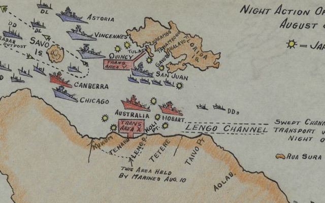

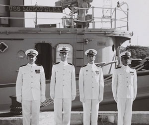

